
Telescope clock drives from the 1980’s or earlier often used AC synchronous motors. These commonly available AC motors are used to power timeclocks, record player turntables, and telescopes, anyplace a motor needed to run at a very accurate speed.
The speed of a synchronous motor is set by the frequency of the powerline, in North America and many other places this is 60Hz. As the frequency must be synchronized for every power station on the grid the frequency is quite accurate, a feature exploited by clockmakers and telescope builders. Once found everywhere these motors are less common, but are still around.
Drive Correctors
It was the common use of these motors in telescope drives that led to the invention of the drive corrector, a device that was once a required piece of kit for serious amateur astronomers. Drive correctors like this were needed when operating from a battery at some remote location, generating AC from a 12Vdc car battery.
You also needed a drive corrector for guiding while doing astrophotography. The corrector could speed up or slow down the telescope drive a bit to correct the telescope drive speed and stay on target, something not possible with the fixed 60Hz of the mains supply. Thus the term drive corrector.
Modern telescopes use stepper or servo motors, operating directly from a 12Vdc source, no need for drive correctors. Thus these drive correctors have disappeared along with the designs to build them.
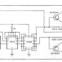
A web search will still turn up a few schematics showing how this was done. Basically a pair of power transistors is used to drive either side of a 12V center tapped transformer. Normally such a transformer would have been used to create +/- 12V power from a 120Vac line. Here it is used in reverse, to create a 120Vac signal from a 12Vdc source.
Yet Another Project
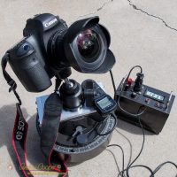
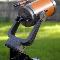
Why do I need a drive corrector? A 1980’s era Celestron C8 mount that needed heavy refurbishment. How heavy? Pretty much a complete rebuild as the paint was peeling off, the grease turned to glue, the declination clutch was frozen, and more. This would require a complete strip down, painting and reassembly.
I considered just throwing the mount out, it was that bad. In the other hand I realized I could use this mount as a camera tracking platform, a time lapse setup, or to mount other small telescopes, maybe as a photographic platform for the eclipse later this year. All it needs is some paint and grease… Right? Maybe a bit more than that.
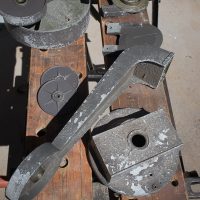
May as well take it apart and check everything out. Things may look bad, but there was no real damage to anything, the parts were quite sound under that peeling paint.
Better yet, the two synchronous motors are operational. Good, as these motors are long out of production and difficult to obtain.
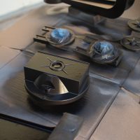
A few hours to wire brush all of the failing paint off, sanding an cleaning the parts for re-painting. Then a few evenings of spray paint coats to create a pile of very nice looking aluminum castings where there was previously a pile that looked like junk.
Building the Drive Corrector
To make the mount operational in the field I would need a drive corrector. Away from any 60Hz AC power line you need to make the AC to power those synchronous motors.
There was also the small matter of an AC power cord connector that was entirely obsolete and difficult to source. This is the old PH-163 style cord that predates the now common IEC-320 cords we use today. I was going to replace the connector anyway, may as well just put a 12V connector in place of the 120V power cord.
A 12V connector? Of course… Just to make this project a bit more challenging I decided to build the entire setup into the base of the telescope mount, not a separate box. I needed to entirely dismantle the mount to renovate it anyway, it was in horrible shape. Why not build some extra circuitry inside the mount before I put it back together?
Technical Challenges
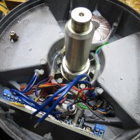
I found a surprising amount of room inside the cast aluminum base, enough for a circuit board and transformer if I was careful. The transformer would mount to one side, the circuit to the other right beside the connectors.
The transformer is the single largest part of this circuit by far, the most difficult to fit within the telescope mount base. Before deciding to make this circuit I needed to source a transformer. No classic square transformer would fit in the needed dimensions, not as long as it was large enough to handle the 10-15VA power level needed by the two motors. There is another option however, a toroidal transformer, often more compact and flatter than a traditional transformer.
What I found was the Amveco or Talema 62052, a 15VA transformer only 25mm high, just the right size! This just might work.
Next step was to lightly machine out the original connector position to enlarge it. This allows mounting of a small plate of aluminum with two connectors and an LED. One connector is the DC power in, a standard 5.5×2.5mm power jack. The second connector is a 1/8″ stereo audio connector to allow connection of a small handpad for traditional drive corrector functions. On the handpad is one button to drive faster, and a second to drive slower. The red LED offers indications for power and low battery alarm.
The old drive corrector schematic shown above uses an LM555 with an RC circuit to set the frequency. This works, but is not very accurate, and may change with time and temperature. The PIC microcontroller offered an internal source, an RC oscillator that could be trimmed for more accuracy, but it too drifts quite a bit with temperature. I wanted a crystal source for good accuracy.
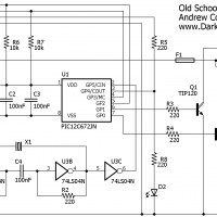
Problem… The PIC timer module is flexible, but can not generate just any frequency, I needed a source frequency that would divide neatly into 60Hz using the limited dividing options of the TMR0 module. A few calculations showed I could not get the desired frequency from a standard 1, 4, or 6MHz crystal.
I began digging through all of the crystals I had on hand and entering the values into a little spreadsheet to do the needed dividing. it took a while, but I found a 1.8432MHz crystal in my stash that could be divided down to an even 1800Hz with the timer module. Dividing by another 30 in software I could get a perfect 60Hz… Success!
Building a simple series resonant crystal oscillator around another old school chip, the 74LS04, created a neat 1.84MHz square wave. Another possible roadblock has been dealt with.
Construction
Technical challenges solved I just needed to build it, and write a bit more code for the microcontroller needed to run it.
The drive circuit is built on a scrap of perfboard left over from a previous project, just enough room for the crystal oscillator, microcontroller, and power supply. The power transistors are bolted to the aluminum case of the mount, this creates a very large heat sink. A few connectors, a small pile of wire to weave everything together, and we have a complete circuit.
I only ran into one problem. I had intended to use the LED to indicate what was going on. Maybe a fast flash for low battery shutdown, slow flash for tracking, etc. No can do, the PIC12C674 has only six pins, I was going to use the GP4 pin to run the LED. Unfortunately this pin becomes clock-out when using the GP5/clock-in pin from the crystal oscillator and cannot be reassigned to general I/O. What? That makes no sense on a very pin limited microcontroller, a bad design decision Microchip!
Code
The code is written in raw assembler, no need for anything fancy here. All we are doing is creating two complementary 60Hz drive signals.
Care was taken in creating the 60Hz signals needed to drive the transistors and the transformer. These signals need to start up properly, no glitches or partial pulses. There should never be a condition that will leave one or another transistor on for more than 20ms. There must be a slight dead time between the two complementary signals. I did a fair amount of testing to ensure this condition is met.
The drive signals are generated entirely within the interrupt routine to ensure completely consistent timing with no jitter.
The fast/slow buttons and the low battery shut-down are not yet implemented. Will get to these eventually… Maybe.
Result
It works! What else can I say. Plug in the telescope mount and the motors come on a few moments later, running smoothly at the correct speed.
For a re-creation of a common piece of kit from decades past this was a fun little project. Now to go out and use it on the sky!

Andrew, good post. Trying to resurrect a nice 10 in Newt from 1952 not used since early 80’s. Drive controller went missing There is good AC power on the concrete table the mount rests on. For a high school astronomy club here in Va. Super low budget available. The RA is a Bodine No767 110VAC motor i think is ok. Do you know where i could find drive corrector circuit to make this work. I think this is a capacitor start motor, but do not know how to hook it up to make it run. I am told i need to switch out the cap once the motor starts. How do I change frequency to vary speed. Any advice really appreciated.
Your issue is a little involved, I hesitate to give any advice without seeing the setup or knowing more about it. I see Bodine motor is still around, unusual when all of the small motor companies seem to have been bought up by the big boys. I would ping their technical support and see if they will help you.
Changing the frequency is changing the AC line frequency. You can build a drive corrector like I did, not much choice as they are no longer commercially sold for telescopes. Or you can buy an AC inverter and modify it to shift the frequency slightly for speed control.
Phil, I.d junk the current drive an move into the 21st century. Check out the OnStep Go2 drive systems onstep@groups.io. These systems are based on easy to build kits, stepper motors and an Andriod phone/tablet or a PC. Excluding the phone tablet cost starts about $30. A 20 year old LaserJet has a nice large step motor.
Very nice. I too have struggled with the 60Hz problem. I like your simple solution. The 3.579545 may also work. Its main application is as the NTSC M color subcarrier in color TVs. Another common crystal is the 3.64 found in infrared remote controls.
I like fooling with the old mounts too. I’ve repaired several Meade LX3 mounts. These also have the corrector built-in the mount. I’ve found a few failures due to the heat thrown off by the TIPs. I routinely replace them with MOSFETs. I use Infineon SPP08P06P P-channel units (-8.8 amps/-60V) mainly because I got a hundred of them for $5 (not PB free). Unlike the TIPS which blow off half the current thrown into them as heat the MOSFETs are very efficient. They will replace the TIPs in your circuit with no other modifications.
Thanks, George
Great post Andrew !
recently I got orange C8 from scrap yard so decided to revive. Hopefully all optics and both SYNCHRON (1 RPH) motors are in great condition ( but not electronics was supplied), so I came to your post. My problem is that I am New Zealand ( ~240V/50 Hz) and the C8 was made for USA but that’s it.
I am thinking seriously about this project, so is there a chance to get your schematics and maybe a list of components?
Also do you have a ready solution for 50Hz modification in the oscillator.
Any help will be really appreciated.
Plamen
Love to see old tech given new life! I acquired a pretty good condition C8 setup with that elusive grey power cable included! I wanted to convert it to run on stepper motors, so I ended up acquiring a second, rough condition fork. It looks like with some modifications, you could get some NEMA-17 motors to mount up in the base, out of sight. I wanted to ask how you mounted the ball head to the RA/base part, however. Did you have a sheet of metal bent into a wide “U” shape, with a mounting hole in the center for the ballhead, and then holes on the sides for where the arms of the fork mounts? Thanks
I machined a plate that went across the top and a couple more pieces that came down from that allowing use of the original fork mounting holes. No new holes drilled into the unit. A heavy piece of sheet metal would work as well, u-shaped, as you guessed.
That makes sense – now that I’m looking at the photo on a computer rather than my phone, I can see that it’s clearly something like 3x 1/2″ aluminum plates bolted together, and to the arm mounting holes. Do you happen to remember what the thread and pitch for where the fork arms mount to the center base? They look like 1/4-20, but the pitch seemed off when I tried a test fit.
Pretty sure they are 1/4″-20, let me check… Yes.
Yes, 1/4-20.
Thanks for the post Andrew. You’re right, schematics for VFO’s are hard to find.
I built mine back in 1974 from the july ’68 issue Sky and Telescope. Input for this unit is 24v. and it is all transistors, no ic’s. I would like to build another that only requires 12v. Am hoping it might be a little more stable than the unit I have.
I was looking at the schematic you posted, and almost all the values are listed except for a couple items, R1 and C1 connecting to the 555 ic. Any chance you might know what those values are?
Again, thanks for the post.
Donald
Oh? You mean to build the old design I posted! I didn’t build that and did not examine all of the details in it.
Hmmm…
I would use an LM7805 instead of the zener/transistor voltage regulator to provide the 5V for the drive circuit.
The SK3024/2N3055 drive transistors could be replaced with TIP120 darlingtons, look at my design schematic.
R1 and C1 set the timing in conjunction with the potentiometer. These are in the standard arrangement for an astable LM555 and docs can be found all over the web. You can play with this https://circuitdigest.com/calculators/555-timer-astable-circuit-calculator. No need to worry about the duty cycle as the 7473 flip flop will solve that, providing a 50/50 duty cycle as well as complementary outputs to drive the two drive transistors. Looks like you need to set the frequency at 120Hz as the 7473 will divide by two.
Using the TIP120’s you could dispense with the 7406 entirely, it is just there as a driver.
Hello
First of all, great praise, great work.
I would like to recreate the electronics for my old C (, but it would have to be set to 50Hz and I don’t know how?
I also wonder what is connected to P1-1 / 4?
Yours sincerely
M.Bartels / Germany
A couple button switches could be connected to P1 to slow or speed the drive by 2x and 1/2x, or more minor changes for one axis guiding. This feature was never implemented in the end.