
How do you power a device that must stay on through an event that may cause a power outage? Battery backup of course. But that answer leads to whole new level of complications. There must be a circuit in place to allow power to be drawn from the battery or the power supply. The proper battery technology should be chosen. You need a another circuit to care for the battery, allowing for very long term reliability. Long term? Years.
What about the charge circuit? A simple charger that can fully charge the battery, but not overcharge the battery is needed. In the case of lead-acid charging is usually accomplished by charging to a chosen voltage before shutting off or lower the voltage to a safe lower value called a “float charge”.
It is in the choice of that voltage that things get complicated. The charge voltage must be above around 2.15V per cell to charge the battery, higher voltages will allow the cell to be charged more quickly. As the voltage and current is increased more care must be taken as to not damage the battery.
Thus many chargers are designed to keep the charging voltage below the gassing voltage. This is made more complicated as the gassing voltage changes with temperature, a higher temperature will lower the gassing voltage. Either the battery temperature must be measured and the voltage compensated, or some assumptions made. Often we simply choose to keep the voltage a bit lower and live with a slower charging cycle.
For this design I chose a 6 volt battery. As the powered device requires 5 volts, this allows the use of a low-dropout regulator and minimal inefficiencies. The assumption is also made that the battery should stay at 20°C or less based on where this will be installed. Thus I chose to limit the voltage to 2.3V per cell to stay below the gassing voltage of 2.4V per cell at 20°C.
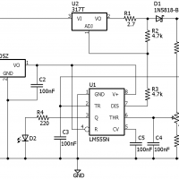
The charger is based on Kenneth Finnegan’s LM555 battery charger with a few key changes. The original design was setup for a 12 volt battery, this could not be used with a 6 volt battery without some substantial changes. The LM78L05 regulator draws power from the input of the charger, not the battery, as the 78L05 needs at least two volts headroom to maintain regulation. The resistors in the voltage dividers were re-scaled for the proper 6 volt charge points.
Keneth’s original circuit uses a level shifter from the LM555 output on pin 3 to shut down the charge current. This extra transistor can be eliminated by using the built in discharge transistor in the LM555 found on pin 7. Pulling down on this line disables the LM317.
Otherwise the circuit functions the same. Placing a 2.7 ohm resistor on the output of the LM317 as shown sets the charge current at a little under half an amp. This was chosen as the charger needed to share a one amp power supply with the remainder of the device.
The potentiometers are adjusted so that the charger shuts off when the battery voltage rises above 7.00 volts and activates when it falls below 6.00 volts. The seven volt upper charge point is chosen to keep the battery below the gassing voltage, which is about 2.4 volts/cell at 20°C, or about 7.20 volts.
A few options are possible here to adapt the charger to the application. A high value resistor could be placed from input power to battery plus to provide a trickle current charge. Re-scaling the output resistors would allow charging of a battery with a different voltage, anything from 4 to 20 volts should be possible. The circuit is suitable for lead-acid batteries only, it does not have the needed accuracy for lithium-ion chemistries.
The reminder here is that the venerable LM555 timer does far more than timing. With it’s high and low comparators, flip-flop, and output stages a creative designer can use it to solve so many problems. For an IC first created nearly five decades ago this simple little device remains a basic building block for any savvy designer.
