
A bad indicator LED, a simple ten cent part brought the Keck 1 telescope to a stop this last week.
I was getting ready to leave the summit when the radio started to speak words of concern, it sounded like something was not working, an instrument rotator?
Worse, the Keck 1 computer room hosted a veritable crowd, from the summit supervisor to all of the techs. Yeah, this was not good, why are they all looking at me? Oh, h%#*!
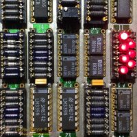
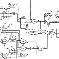
My boss, Steve gives me a good description of the problem while I leaf through the schematics binder looking for the right page. Here, the auxiliary amplifier assembly logic card, page 2.
The room is a mass of confusion, ideas called out, things checked. Tomas is on the other end of the phone assisting by operating the computer end of the system and offering yet more suggestions. I give Joe a nod of thanks, his unflustered attitude an nice contrast to the chaos as we plunge into troubleshooting, handing me the DMM.
We work our way through the obvious issues. Indications are good from the telescope. All of the fault lights on the logic card indicate things are OK, in conflict with the bright red LED on the amplifiers indicating they are disabled.
We can move the rotator in manual mode. Good! This shows the amplifiers, motors and limit switches are fine. The system will just not enable the amplifiers under computer control mode.
It is follow the circuit time, jumping from chip to chip across the board. Tracing the circuit I came to a node where the voltage was 9.36v. Check that again? Yup! In this CMOS logic circuit the voltage should be either near 15v or very near zero. An intermediate voltage is just not supposed to be there.
In classic CMOS logic a high is defined as a voltage at least 70% of the supply voltage. With a supply voltage of 15v this requires at least 10.5v to be a high. 9.3v is close, maybe close enough to work much of the time, maybe not working sometimes.
Fine, this connection is driven by the IC in location F14, just need a spare DS3632… Replace it! That should fix it…
Maybe one of the loads is pulling it down, only two choices, F15 and F7. At least all of the IC’s are socketed and we have a decent supply of spare chips.
Nope. Not those chips either. That is everything connected to the circuit.
What the heck? Let me look at that circuit again.
If memory serves the DS3236 driving this circuit is an open collector output, it needs a pull-up to go high.
It has one, an LED and resistor that also form the limit indicator. When the clockwise limit is reached the LED illuminates. The LED is not on, not a problem right?
The resistor is an old carbon composition resistor, those things are armageddon proof. You have to try to kill one, not happening in a properly designed circuit.
The LED however… “Nick, can you get me a 5k resistor from the lab?”
Hold the resistor on the leads of the chip and the voltage pulls right up and the amplifiers enable properly.
The LED in question is probably three decades old, dating to around 1990 when these logic boards would have been built. LED’s of that era were frankly not very good by today’s standards. Downright anemic in light output and failure prone.
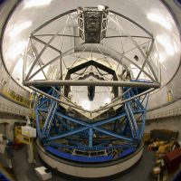
Why is the rotator critical? The really big telescopes are alt-azimuth, the axis of telescope motion do not line up with the rotation of the Earth and sky. While this is structurally much easier to build it causes the field of view to rotate as the telescope tracks. Thus the instrument needs to have a rotator that keeps the stars stationary on the detector. You either build a set of rotating mirrors into the instrument, or simply rotate the entire instrument to cancel the motion of the sky. That does not seem too hard until you consider the instrument can weigh many tons and the rotator bearing is two meters in diameter.
Simple description of the problem? The LED is used as a pull-up, without which the logic gate output would not rise to a proper high level, thus the instrument rotator servo amplifiers would not enable. No servo amplifier means the rotator will not rotate. No rotator equals no science data.
So yes… One of the world’s largest telescopes, 370 tons of steel and glass, was brought to a halt because of a bad indicator LED.
This whole drive system is due to be decommissioned last year. Yes, things are running behind schedule. The new drive control system is getting close, in use about half the time as we work the bugs out. We just need to keep the old system running for a wee bit longer.
We were only two hours late in leaving the summit. At least the view was pretty, just after sunset a soft alpenglow illuminated the mauna and the road home.

I’m a bit surprised the designers trusted an LED that late – by the mid 1980s I was well aware of them going either O/C or S/C for no obvious reason.