
With the Keck Observatory open house approaching I am helping get one of the most popular activities ready. At the last two open houses we have made flasher pins, we will do so again this year.
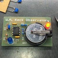
The PCB is configured as a pin or badge, with a brooch pin soldered to the back that also serves as a switch to turn on the LED’s.
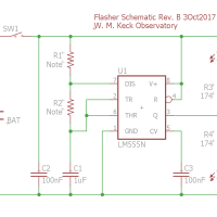
The original design came from John Maute at SAO. The circuit is based around the venerable LM555 timer IC configured as an astable multivibrator. The LM555 timing circuit is simple enough to solder together in a few minutes, complex enough to look cool and provide a real introduction to an electronic circuit.
A lithium coin cell provides power, lasting for about a week of continuous flashing with a fresh battery. With this battery the 555 timer needs to be a low voltage variant like the LMC555 or TLC555 in order to operate on 3V. The battery is just enough voltage to drive blue and pink LED’s that require at least 3V to illuminate.
The fun trick in the design is the brooch pin. The back of the pin is cut in half with a small section removed from the center. You can then solder both halves to the flasher PCB so that the pin can again be fastened. By separating the two halves you create a switch that is closed when the pin is closed, turning the flasher on.

Shelly figured she could simply send a photo to a PCB vendor and order the boards. The result was rather understandable “Can you send us some Gerber files?”. I can only image what other reactions they were tempted to respond with.
Cleanup of the Design
We needed a new PCB layout.. While I was doing that I made a number of improvements to the layout to simplify construction. I put the two LED’s in opposite corners of the PCB, mostly because I think it looks better.
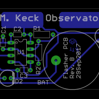
The original design had the battery holder hanging half off the PCB, fixed that. Designed for a smaller 2032 button cell battery, these are vastly cheaper at about $0.25 each, rather than a dollar each for the 2430 used previously.
Getting the Parts
The PCB was sourced from China via SeeedStudios. Seeed is a favorite source for hobby PCB’s lately, no surprise, the cost was a fraction of domestic PCB houses and the service was quite good.
I ordered a handful of batteries first as PKCell was a brand I was not familiar with. The batteries turned out to be just fine, the sample I tested lasting almost a full week in the prototype flasher I built up. Just order another 150 parts!
Total cost for the PCB is coming in at $2.61 each in 100 quantity. Surprisingly the battery holders turned out to be the most expensive part, even more than the PCB itself.
| Item | Description | Source | Part# | Cost |
|---|---|---|---|---|
| PCB | 2″ x 1.25″ Flasher PCB | Seed | 0.38 | |
| U1 | TLC555D timer IC | Digikey | TLC555CP | 0.56 |
| C1 | 1µF 25V X5R capacitor | Digikey | FG26X7R1E105KNT06 | 0.07 |
| C2,C3 | 100nF 25V X7R capacitor | Digikey | SR201C104KAR | 0.16 |
| D1,D2 | Red, green, or amber LED | EBay | 0.03 | |
| R1,R2 | ¼W 5% resistor, see text for value | Digikey | 0.02 | |
| R3,R4 | 150Ω ¼W resistor | Digikey | CF14JT150RCT | 0.02 |
| BAT | CR2032 lithium coin cell battery | EBay | CR2032 | 0.27 |
| BAT | 2032 coin cell battery holder | Digikey | BS-3 | 0.73 |
| SW1 | Brooch pin (see text) | S&S | JE163 | 0.14 |
| —- | ||||
| 2.61 |
Below I have provided both the Eagle source files and the Gerber CAM files if you want to make the Flashers. Note that the silkscreen text says Keck Observatory, you might want to change that.
Flasher Source Files
Flasher CAM
These flasher boards have always been the most popular activity at the Keck Observatory open house. I expect this year will be no different. Looking forward to a day of kids and soldering irons… What can go wrong?
