I have had a problem observing here in Hawai’i. The skies can be gorgeous, there is little to no light pollution, and you have access to much more of the southern sky. What could go wrong? …Dew!

I had one dew strap available, given to me by a friend and fellow observer, a small one just right for wrapping around an eyepiece. So I just needed a controller to get started. There are several of these available on the market. But I had some issue with the cost, it seemed a bit high for what was essentially a very simple device. Some of the commercial units offered features like temperature sensing and regulation. Simple overkill for most users actual needs, just warm the optic slightly until the dew goes away. Sounds like an excuse for another evening project to me… Build it!
OK, it did take a few evenings to do all of the wiring and testing. But I enjoy that. The design is based on a simple schematic I found at Backyard Astro based on a design by Chris Heapy. I considered more sophisticated designs, even played around with a high frequency switcher on the breadboard. But in the end I decided that simple is all I needed and the basic LM555 low frequency design would work just fine. Some have complained about electrical interference from dew heater controllers. A design using a simple bipolar transistor based device can be easily tamed with a couple simple precautions to reduce interference.
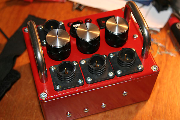
I managed to build the entire device with parts and pieces I had on hand. Instead of a single channel device I put three channels in place. I figured I would need at most three channels to cover the primary, secondary and eyepiece in a practical setup. The size of the box I had also limited me to three channels, as this was all the panel had room for, even then the layout is a bit tight. I did add one more feature to the design, a low voltage cutoff to prevent deeply depleting the battery and possibly damaging it. A simple zener diode and transistor circuit tied to the reset pin of the LM555 accomplished this. The controller will shutoff if the voltage falls below about 8 volts.
I build things tough for field use. In this case this meant a cast aluminum case, heavy connectors, steel handles at each side to protect the face plate and the controls. One item I can not abide in the commercial dew controllers is the use of audio RCA connectors for power, a very poor choice of connector. RCA connectors can be easily shorted out, a danger with a battery power supply, they do not latch, and are often cheaply made. For my field powered gear I use Amp CPC series connectors. These are cost effective plastic versions of the military style barrel connectors. They latch and are keyed to prevent reverse connections, both good precautions when using gear in the dark.
So now I just need to order a couple more straps for the various telescopes and I should be in good shape next time out. Looking forward to some proper field testing!


Please post a photograph showing a mounted strap or two on one of your telescopes.
Thanks
I loved this circuit, I’ve buit several and need to build some more and noticed your note about a low voltage cutoff. Do you have a schematic of the circuit? Also how can this be adjusted to cutoff at 10.5v instead of 8v.
Thanks
I am forgetting at the moment how I implemented a low voltage cutoff on the circuit, my notes are at home. On the other hand it is easy to do… Simply use the reset pin of the LM555 to implement. The reset will hold the output low if you pull pin 4 low on the LM555. Either buy a voltage monitor IC, or build a voltage monitor (a zener diode and transistor combo? A voltage reference and a comparator like the LM311?) that will pull the reset pin low at your selected voltage to protect the battery.
Thanks for the quick reply. I understand pulling pins low and some of the other things but since I’m not too much of whiz with electronics though. so if I connect the transistor to pin 4 and ground and the base through the zener diode to 12v bus. How would I adjust the cutoff voltage?
Thanks