With the Keck Observatory open house approaching I am helping get one of the most popular activities ready. At the last two open houses we have made flasher pins, we will do so again this year.
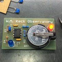
A simple electronics project… The Flasher PinFlashers? These are a simple circuit built on a PCB that flashes a pair of LED’s. Nothing serious, just a bit of electronics fun. The activity allows folks to learn a little electronics and soldering.
The PCB is configured as a pin or badge, with a brooch pin soldered to the back that also serves as a switch to turn on the LED’s.
The original design came from John Maute at SAO. The circuit is based around the venerable LM555 timer IC configured as an astable multivibrator. The LM555 timing circuit is simple enough to solder together in a few minutes, complex enough to look cool and provide a real introduction to an electronic circuit.
In this ever complex world in which we live the rules are always changing, and usually getting more complex. A modern, information society has many rules that govern who owns what. Copy a photograph from the web and you are probably breaking the laws concerning copyrights. There is a complex and sometimes contradictory set of laws that governs all manner of ownership in this technological age.
The engine on a hay baler offers a view of mechanical paraphernaliaDo you know the rules?
Buy a CD with your favorite tunes… Can you copy the tracks onto your phone? Can you create a video with the music and post it to YouTube? What about that expensive photo software package? Can you put it on your laptop and desktop? The rules are often complex, and often the answer is not clear cut.
Increasingly we do not actually own what we buy. At least that is what many corporations will tell us.
You would think that the answer is easier if the thing we are talking about is a physical object. If you buy a car, can you re-paint it, install a new stereo, or ignition system. Of course you can do that. Can you? Sometimes the answer is no.
Increasingly corporations attempt to maintain control of a product after the sale. They use many tools to do this. One is intellectual property, copyrights and copy protection on the software that is now embedded into many of the things we buy.
It does not happen very often, but it does happen. Driving up to the summit in the night to fix the telescope. As an operations engineer it is part of the job, but I can think of only a handful of times in my decade on the summit I have actually done it.
The motor controllers for the Keck 2 top shutterConsidering it takes the better part of two hours to get to the summit there is no point in trying unless the issue occurs early. You have to consider the issue… Can you fix it in the middle of the night? Will there be any night left once you fix it? Do you just call the night and head up the next day with a full crew and a good night’s rest to fix it properly?
This particular problem was discovered first thing upon opening. Well? Lack of opening for the night. The top shutter on Keck 2 would not move, fault lights all over the place. Hard to look at the sky with the top shutter closed. I worked the issue over the phone for a while with Nick as far as we could.
The conclusion? I would have to work the problem in person to fix it, I have to go up.
Can I fix this? Probably. I found myself leaving the house before 9pm for a run to the summit.
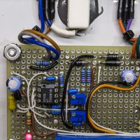
I was looking at some photos and realizing how much perfboard I have used in recent years. I routinely find myself building small circuits, and that process almost always begins with grabbing a bit of perfboard from the supply stash.
Hand wired point-to-point wiring on perfboardPerfboard is the basis of point-to-point wiring and has been around since well before I started in electronics as a young teenager. It is generally a small circuit board with holes drilled in a 0.1″ grid.
The holes are usually about 0.042″ and will accommodate a wide range of electronic components without modification. Cheap perfboard will have no copper pads or traces, good perfboard will have a pattern of copper traces and pads to which you can solder your components. Better yet is perfboard with plated-thru holes and pads on both sides.
A minor code revision as I slowly get everything working properly. I am adding new modules as I need them for other projects.
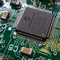
The microprocessor on a GenPIC PCB assemblyThe latest GenPIC deployed will be a coolant valve controller that allows remote control of some glycol valves in the AO bench. It is a pretty simple device, just four relays with some automatic timing rules and a serial control interface.
In the process I added support for the service connectors including parallel and simple serial modules to the GenPIC code base, may as well release it. Thus you get code release 0.2…
Next up will probably be SD card support, I have a project that needs to be finished requiring some reasonable data storage. Just ordered a few micro-SD card breakout boards from SparkFun
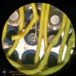
How do you power a device that must stay on through an event that may cause a power outage? Battery backup of course. But that answer leads to whole new level of complications. There must be a circuit in place to allow power to be drawn from the battery or the power supply. The proper battery technology should be chosen. You need a another circuit to care for the battery, allowing for very long term reliability. Long term? Years.
A 6V lead-acid battery charger based on the venerable LM555.A good answer for the battery technology is sealed lead-acid. A properly used lead-acid battery should last a decade or more while providing power to operate for over a day. Lead-acid may not be a good choice for a portable device where weight and size are the primary considerations. But for a stationary application this venerable technology is a good choice.
What about the charge circuit? A simple charger that can fully charge the battery, but not overcharge the battery is needed. In the case of lead-acid charging is usually accomplished by charging to a chosen voltage before shutting off or lower the voltage to a safe lower value called a “float charge”.
I have had hardware for a while now, it is about time I release some firmware that actually runs it.
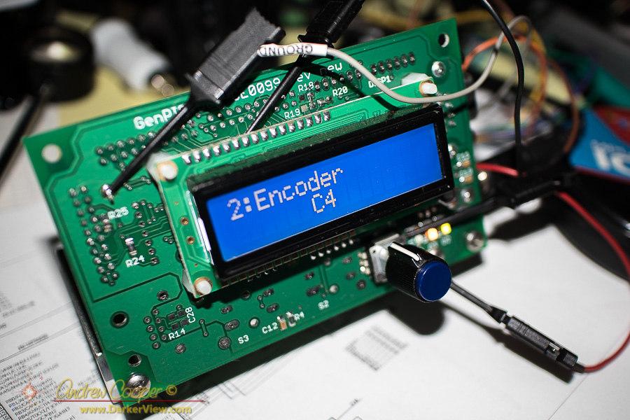
The development setup in use generating the first software release for the GenPIC utility PCBHere it is!
The first GenPIC code revision is a test and demonstration release. It contains support for one serial port, an LCD character display, user input including the encoder and pushbuttons, the indicator LED’s, timer generation, analog input including onboard temperature readout.
Also included is a serial command interpreter implementing a serial interface usable with any serial terminal. There is also a user interface system with a state setup that provides multiple input screens. This should handle a wide array of basic control capabilities, either using the serial port or through using the LCD screen and the encoder.
The code allows you to exercise many of the basic functions of the hardware and provide a framework on which a real application can be built.
It works, it runs, it looks fairly good. Now time to make something useful with it…
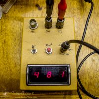
I have been messing about with electronic circuitry for almost four decades. I recently came across an early example of my work. The device is a digital event counter built around classic 74xx series logic. A chain of 74190 decade counters feed a set of 7447 decoder drivers and seven segment LED displays. A plastic project case with switches and connectors reminds me I have been building little devices for a very long time.
A digital event counter built when I was fifteen years old.In some ways the unit is very similar to one of my more recent builds. Perfboard and point-to-point wiring are still standard construction techniques. The technology may have changed across the years, becoming far more complex, but some parts have remained the same.
The Keck Adaptive Optics systems are workhorse scientific instruments. Equipment that has resulted in so many great astronomical discoveries. The AO systems have also seen a great deal of improvements and upgrades through the years. New computers, a new wave-front controller, guide star lasers added, new cameras, different science instruments, and much more.
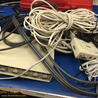
A pile of electronic cruft removed from the Keck 2 AO enclosure.While the new gear has improved the systems dramatically, the result is that there is a fair amount of disused bit and pieces hanging about. Mostly cabling, but more than a few unused boxes of electronic gear are still sitting in place in the racks.
Eventually I just get fed up with it and insist we spend some time getting rid of it. With no AO use scheduled for a while there is a chance to spend a couple days ripping out this pile of cruft. Identifying and removing unused boxes. Following cables to nowhere, wire cutters in hand to snip away the multitude of nylon zip-ties.
We remove three large armloads of cables and other gear, carring the pile down to the electronics lab for sorting through and disposal. Most of it is horribly obsolete, things like KVM’s for PS/2 style mice and keyboards, or cables for old Sun computers. Most of it will simply be thrown out. It feels so good to get it out of AO and to clean up the place a little.
I called this pile of junk cruft, a word that drew funny looks from my co-workers. You don’t know what cruft is? What sort of nerds are you? Sorry, cruft is what I have always called leftover technical junk.
Cruft is jargon for anything that is left over, redundant and getting in the way. It is used particularly for superseded and unused technical and electronic hardware and useless, superfluous or dysfunctional elements in computer software. – Wikipedia
It turns out that the word has a long history in engineering and computer science with a heritage that includes MIT and Harvard. It is indeed the proper word for the detritus that had been accumulating in the AO vault.
I am no stranger to point-to-pointwiring. I routinely use the technique to build small circuit boards. Well done point-to-point is a permanent and reliable way to build a complex electronic device.
Welded point-to-point wiring on a complex circuit board
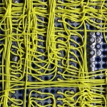
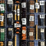
But then there is this circuit board assembly I came across… At first glance it looks like a wire wrap board. But there are no posts, the wires are flush to the board. Neither is it traditional point-to-point wiring, the wires are not terminated to solder pads beside the pins being connected. I had never seen a construction technique like this.
The board is an old PCB assembly found in a storage cabinet while clearing out the old junk that has accumulated about the observatory. No idea where it came from or what it was used for, the only clue is some writing on the box… “Keck level shifter”, Perhaps a piece of a detector controller? Someone clearly put a lot of work into the board at one time, now it sits in my office as unknown junk. It is the odd construction technique that caught my eye and led me to hang on to the board, at least temporarily. What is this?
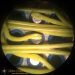
A closer look under a microscope shows a connection clearly made by some sort of spot welder. There is a neat little hole through the insulation at each connection. Stripping back the insulation reveals a very neatly welded wire. Each wire is welded to the flat bottom of each pin socket. Every component pin is socketed, this includes all passives, which are mounted to headers and plugged in alongside the IC’s.
There are a number of advantages to this wiring method… The connections should be very reliable and robust, the weld is a nearly ideal electrical connection. As no connection pads are needed beside each socket the density is much higher using less circuit board real estate per component, you can cram more on the board. Interestingly the connection technique can be used without terminating the wire, daisy chaining to the next connection point.
There are disadvantages as well… The method clearly requires some sort of welding equipment with perhaps an automatic wire feeder and cutter, a built-in microscope for positioning the weld, and more. Clearly an expensive piece of kit. No components can be present during welding as they may suffer damage from the high electrical currents needed for spot welding, thus everything must be socketed. All those little sockets are expensive! Rework or repair would need to be done with more traditional soldering techniques.
I would love to see the machine that did this board assembly. Maybe even a chance to use it. More information on the process seems difficult to find on the web without a trade name or other keyword that would clearly identify the process.
Not that these welded wires would be of much use today. The technique is clearly ideal for complex digital circuits of the style and speed that was common through the 1980’s to around 2000 or so. After that the prevalence of surface mount technology and the abandonment of the DIP package would doom the method. Modern high speed circuits benefit greatly from the more controlled traces of a printed circuit board and would not fare well on a welded wire board. In these days of easy computer layout and cheap printed circuit boards welding would not be my fabrication method of choice.
Welded point-to-point wiring on a complex circuit board
Detail of a connection in welded point-to-point wiring on a complex circuit board
Detail of a weld in welded point-to-point wiring on a complex circuit board
Component side of a welded point-to-point circuit asembly