
The usual engineering minutia takes up much of my week… Paperwork, documentation, purchase orders, meetings, etc. There are the occasional chances to just have a little electronic fun. Thus I greeted a request from a couple of our support astronomers with some enthusiasm. They needed a variable intensity light source for calibration of the OSIRIS spectrograph. This source sits inside an integrating sphere on the AO bench along with four spectral sources, small tubes of neon, argon, xenon and krypton.
I set aside a bit of time each day to design and build the source. The last couple hours of the afternoon are best, at this point I have had quite enough paperwork. A chance to practice my trade sketching out the circuit, or simply sitting at the bench and soldering… Perfect.
The white light source is a simple incandescent bulb. In this day of LED, florescent, HID or other high tech lamps it seems archaic to use an incandescent. You must consider that OSIRIS is an IR spectrograph, a source that radiates across the IR spectrum is ideal. This is something an old-fashioned thermal source like an incandescent bulb is perfect for.
Much of the design was a recycle of an earlier project, this includes 80% of the code needed to do the job. The previous design had driven a few bright LEDs with a constant current, all I really needed to do was up-rate the power available to support an incandescent bulb.
All of the original testing was done with a halogen bulb. This was my first thought when putting things together. But I remembered something I had been told years ago about halogens, something that had me checking the references to refresh my memory. Halogens need to operate hot! Get them hot enough and a little bit of chemical magic takes place with the gas and vaporized tungsten. The tungsten gets deposited right back on the filament, giving the lamp a very high lifetime in a temperature regime that would otherwise quickly destroy the filament. Problem! Operate the lamp at much below the rated power, say more than 10% under, and this feature stops working resulting in very short lifetimes.
This design would operate across a range from barely glowing to full on for the lamp. Not the right range to operate a halogen bulb. Time to dig about in the parts stockpile and come up with ordinary, non-halogen bulbs. Yeah, the stockpile is that good, a package of bulbs and a socket to match quickly located.
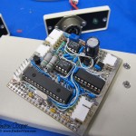
Construction is quite straightforward. A bit of perfboard provides a home for the bulk of the circuit. All of the parts were available as DIP packages, better yet all parts were on-hand! OK, it is an ancient PIC16F873 micro-controller I located for the job, not even the A version! No matter, it has more than enough horsepower for this simple job, I just have to remember how to write code for it. The rest of the parts come from my own stockpile or raided from the lab at work. No order to Digikey this time.
The two power transistors are not on the perfboard. As this is a linear design they dissipate a substantial amount of heat. Instead the TO-220 package transistors are bolted to the aluminum case and connected via a small wire harness. Power dissipation is about 4 to 6 watts.
Stability proved to be the biggest obstacle to a finished design. While the current regulator appeared to operate properly at first glance, a closer look showed the current oscillating 20-40% at 26kHz. Oops? Time to do a little more thorough analysis. A spice model showed exactly the same condition as the actual hardware, a bit different frequency, close enough. The bode plots showed the lack of phase margin I expected. Add a capacitor here, shift a resistor value there… Stable! Sounds simple, in reality it took a couple hours of frustration and trying different things. The obvious ideas I tried first didn’t work.
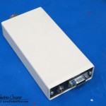
The finished device is now installed in the Keck 1 adaptive optics bench. Initial testing shows all is good, the instrument specialist is happy with the light and thankful for the control. It is a bit dim through some of the Z-band IR filters, I may want to look into finding a different bulb other that what I had on-hand. The setup should handle a wide range of lamps without modification.
