Tag: mirror
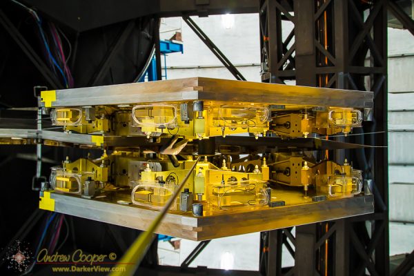
Jacked
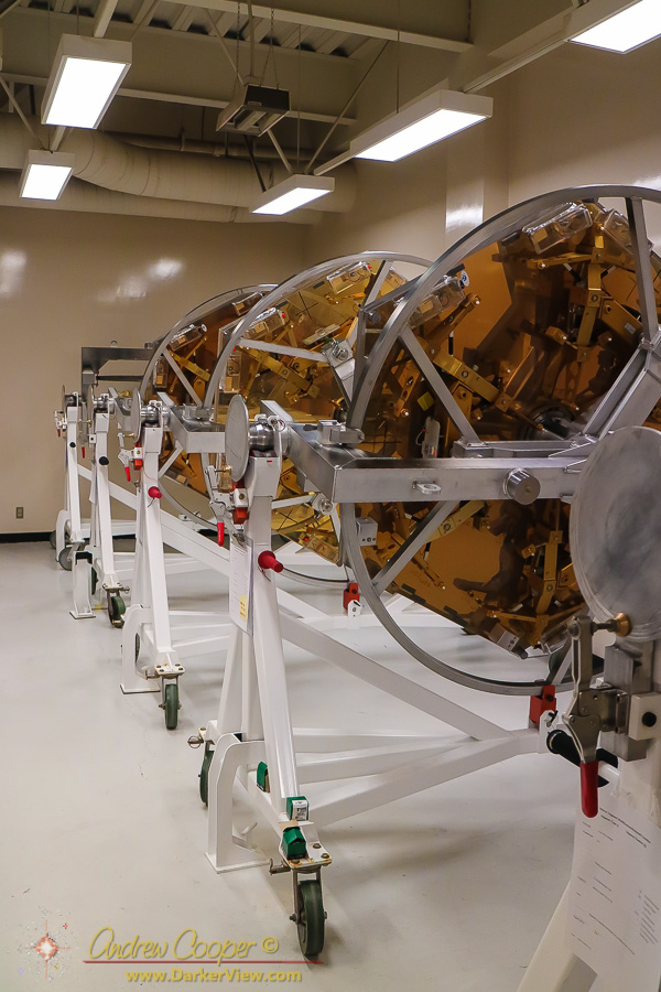
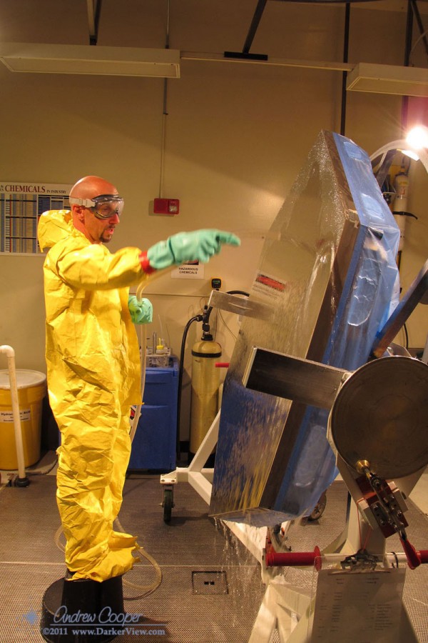
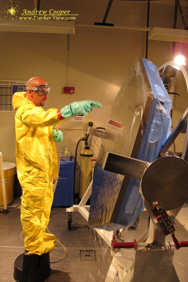
Segment Storage
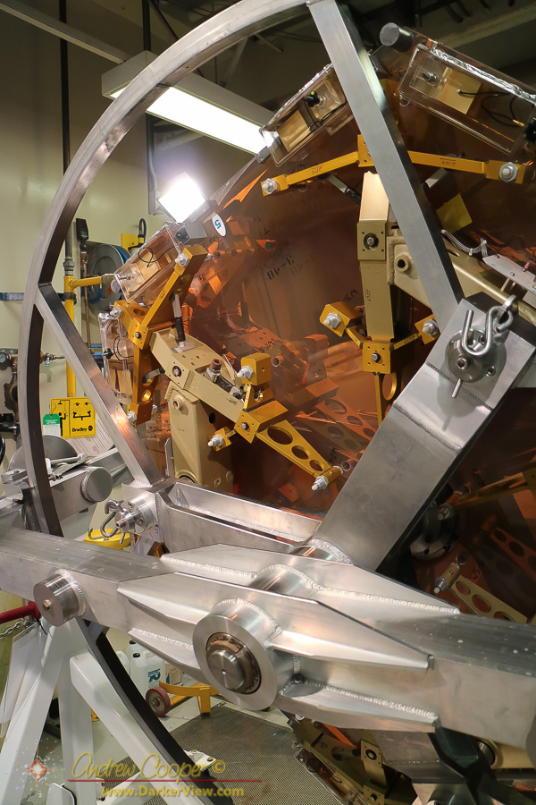
Segment
A Secondary Mount
The secondary mount is often one of the most complex pieces of a telescope build.
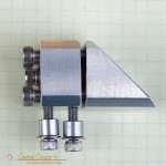
The mount must be small, not blocking any more light than the secondary mirror. It must be adjustable to allow tip, tilt, and centering of the secondary mirror. it must be rigid, able to hold the adjustment precisely once the telescope optical alignments are made.
Thus I have put together a new design for myself, to be used in the 6″ travel ‘scope under construction. The design is simple and robust, a pretty solid little device using the lessons I have learned across the years. It draws upon ideas from many other secondary mounts I have seen.
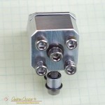
The body is square as this is easier to clamp during each of the manufacturing operations. The square is as large as possible to provide a stable mount, with the corners beveled just enough to stay behind the secondary.
The mount shown here is designed for a 31mm minor axis diagonal mirror. Thus the body of the mount is one inch square with 0.1″ beveled off each edge. This could be scaled up or down for another size diagonal mirror. The overall length of the entire mount is as short as possible. A bar of aluminum was cut to size and beveled first. A four inch bar yielded two complete mounts. I left the machined surfaces a bit rough to break up the smooth surfaces, better to hold paint and to avoid reflections.
There are four adjustment screws here. This allows for a simpler adjustment scheme than a three screw arrangement. With three screws adjustments are often made using all three screws at once. A four screw scheme allows the screws to be adjusted in pairs to effect moves in one axis at a time.
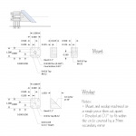
I have made mounts with spring loaded screws in the past. They are easier to adjust, no need to loosen and tighten opposing screws. But they are not as rigid, the careful adjustment more likely to drift. This mount uses pusher screws that must be loosened and tightened in pairs.
Shallow pockets are drilled into the rear of the wedge for the tip of each adjustment bolt. this prevents any rotation of the wedge as long as the adjustment bolts are tight.
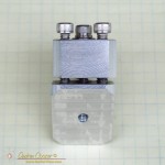
Vertical adjustments will be made by adjusting the height of the standoffs used to mount the secondary, or perhaps by shimming with a washer or two. The two mounting screws will sit in slotted holes allowing the secondary to be aligned with the focuser.
The center screw sits in a counterbored hole, only a small section of the shaft near the head is constrained. This allows it to tip slightly and allow the adjustments. A split lockwasher keeps some back tension during adjustments.
The secondary will be attached with RTV adhesive. The corners of the mount line up with the edges of the secondary making alignment quick and simple. All that is needed is a coat of flat black paint on the sides to prevent odd reflections in the optical path.
Warped
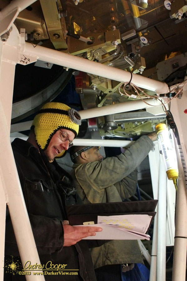
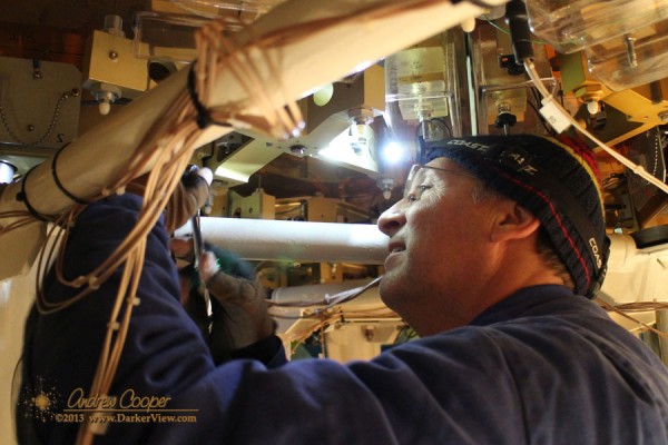
Warping is not much fun. Warping is now on my list of responsibilities. At least I know I am accomplishing something critical to the operation of the telescope.
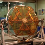
Exchanging segments does require some interesting procedures to realign each new segment, each must be warped and the edge sensors tuned. The first few hours of the night after a SegEx is used to evaluate the performance of the newly replaced segments. Using a special alignment camera system the optical figure of each segment can be evaluated and a set of corrections generated to be applied the next day… Warping.
To apply the correct pressure there are small knobs and screws at specific points in the whiffle tree. Each adjustment point also contains a strain gauge, allowing the applied pressure to be measured precisely. A computer and analog interface allows all of the points to be read out and checked against the calculated values.
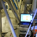
After setup, it takes about an hour to do each segment, an hour of painstaking frustration. the mirror cell is just the right height, too high to sit down and reach the knobs, too low to stand up fully. Working in a jungle gym of frigid steel just makes it worse. A day in the mirror cell is a nice recipe for a tired and sore body.
How careful was I? Did I get all of the points set correctly? The computer is displaying all of the correct numbers. I will not know until the next day, when the night’s performance data is reduced, when we can see the figure of the primary mirror and check the errors.
My first warp is a success, most of the segments show less than 20nm rms error. Next SegEx there are only two segments being exchanged, but Sergey is threatening to have two others re-warped to address some lingering issues. Four? Better than six. Only 360 adjustments to make, more or less.

