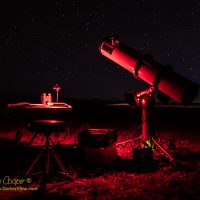
The classic Cave Astrola telescope has become my roll-out, quick observing session ‘scope, often found in my driveway. I have also used it a few times at darker sites when I expect the weather to be damp or dewy as a Newtonian is more protected.
The restored 8″ f/6 Cave Astrola under a dark sky at Kaʻohe
While the restoration job was finished some time ago, I never got around to re-coating the optics. Meanwhile the telescope has seen good service on many occasions as I enjoyed this fun-to-use instrument.
The optics did need some attention… The primary mirror from the Astrola appeared to have not been re-coated since it was made in 1978. Thus the aluminum coating was over 40 years old. While the coating looked bad, it was still serviceable, producing reasonable images.
Still, the loss of light due to the old aluminum coating was probably reducing the effectiveness of this 8″ telescope to something more like a 6″ telescope. I had meant to get it re-coated some time ago, but we know how these things work.
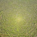
It was pretty obvious, an odd bright spot in the trees below that followed the helicopter. Having educated myself on quite a few optical phenomena I knew exactly what it was I was seeing, and made a point of taking a few photographs.
A bright spot in the Puna rainforest caused by the opposition effectThe mechanism for this bright spot is remarkably simple… No shadows.
Called the opposition surge, Seeliger effect or shadow hiding this simple optical phenomena occurs when looking at rough or irregular surfaces that are directly away from the light source, usually the Sun. On an irregular surface some parts will shadow other parts, resulting in an apparent darkening of the overall surface. When looking at that part of the surface directly away from the light source no shadows are seen, making that region appear brighter.
The tropical environment of Hawaiʻi is not kind to optical instruments. Tropical humidity can cause a host of issues ranging from corrosion of metal parts to decay of wooden and cardboard telescope structures. For those of us who build and use small telescopes the issues of tropical heat and humidity are rather concerning.
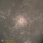
Fungus colony on a small achromatic lens surfaceWorst of all is the fungus. Impressively there are species of fungus that can grow and thrive on clean optical surfaces. It is hard to imaging a more hostile place to grow, seemingly devoid of nutrients and the moisture necessary for life.
I have seen camera lenses lost to the white fungus. A friend once showed me a Canon 70-200 f/2.8 L, a $2000 lens, with fungus covering internal elements. Even on the “dry side” of Waimea the humidity was high enough to allow fungus to destroy this lens.
The problem is not an issue on the summit of Mauna Kea. The high altitude air typically exhibits a relative humidity of less than 10%. Several references note that a humidity of above 70% is needed to promote fungal growth on optics. We see no issues with fungal damage to the mirrors or instruments on the big ‘scopes.
Below the tropical inversion layer (about 6-7k feet) it is another issue entirely. Near sea level, where most of us live, humidity can remain above 80% much of the year. The warm and humid conditions of these islands are idea for growing anything, including the omnipresent fungal gardens that create the smells of a tropical landscape. Fungus is inescapable in this world, the spores drift on the wind and an stay dormant for decades, anywhere conditions are suitable fungus will grow.
The possibility of equipment damage was a major element in our buying a house. Waikoloa is located within one of the driest areas of the island. The humidity typically hovers in the 50’s, dry enough that I have had no issues with the multiple telescopes stored in the garage. Still, I do inspect stored equipment periodically, looking for the dreaded white fungus or other damage wrought by this tropical climate.
It is not a single species of fungus responsible for the problem. Apparently quite a few species are able to colonize an optical surface. Looking through the literature I find referenced to multiple species that can grow on optical glass…
The fungi which grow in optical instruments belong to the groups Phycomycetes, Ascomycetes and Fungi Imperfecti. The following species were frequently isolated from instruments which had been in New Guinea: Penicillium spinulosum, Thom.; P. commune, Thom.; P. citrinum, Thom.; Aspergillus niger, Van Tiegh.; Trichoderma viride, Pers. ex-Fr.; Mucor racemosus, Fres.; and M. ramannianus, A. Moeller. So far, Monilia crassa has not been isolated from Australian instruments, although Dr. W. G. Hutchinson (5) of the United States, found this to be a common species in the Panama zone, and it has also been recorded as frequent in West Africa by Major I. G. Campbell. – J.S. Turner, et al.1
I admit that the fungus can be pretty, in an odd sort of way considering the damage. Under a microscope it appears lacy, the mycelium fibrils growing across the glass in search of more nutrients to support the colony. In the center small round fruiting bodies are the launching point for new fungal spores.
I recently had another round of battle with fungus while restoring a collection of instruments that had been stored in a garage on the side of Hualalai. The high humidity had wrought impressive damage on both the optics and metal components of the telescopes. And there is fungus! Found in the eyepieces and on the telescope mirrors. During the cleaning and restoration of the instruments I found it necessary to completely dismantle many optical assemblies just to remove and kill the fungus. I some cases I was in time, but not completely, it is not without regret that I throw a $400 eyepiece into the trash.
Dealing with the fungus is imperative, cleaning and killing the growth before severe damage can be done may save the equipment. If the growth is severe enough the glass surface and the coatings can be damaged. Apparently the fungi can excrete hydrochloric acid, etching the surface and creating permanent damage.
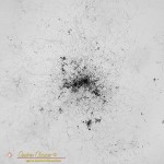
Fungus colony on a small achromatic lens surfaceMinor damage may not be enough to ruin the device. It actually takes a great deal of damage to appreciably affect the performance of most optics. A few small specks of damage remaining on the surface after cleaning may not be noticeable. Inspection of each spot of damage with a microscope can be useful, Sometimes it is clearly damage of the surface and irrepairable. I have also found hard deposits that at first glance appeared to be damage under the core of fungal colonies that remained after cleaning. These may be removed using a soft wooden tool like a toothpick or chopstick.
Killing the fungi requires a solvent that will both kill the fungus while not damaging the optical surface. I find references to both alcohol as well as other solvents. A mix of 50/50 hydrogen peroxide and ammonia is recommended by some references. Along with cleaning the glass I am careful to soak all of the structural elements as well. The tube, the spacers and lock-rings can all harbor minuscule colonies or spores awaiting suitable conditions to grow again.
Optical fungicide solutions tend to be expensive and hard to obtain, but they are available from some optical equipment manufacturers. Alternatively, you can use a 50/50 mix of hydrogen peroxide (H2O2) and ammonia (NH3). Usually, 5 ml of each is adequate (10 cc in total). Mix just prior to use and do not store the mixed product. – Ismael Cordero, Community Eye Health Journal2
Living in a warm humid environment one must be vigilant and ready to deal with issues when found. Examine optics regularly, keep a can of WD-40 next to the tool box (and use it), store optics and electronics with plenty of ventilation and reduce the humidity to well below 70% if needed. Extra vigilance to preserve valuable equipment is the price of living in paradise.
With Jupiter still near opposition and Mars opposition approaching I would like to do a little high resolution planetary imaging. For planetary I use our Nexstar 11″ telescope, with 2800mm of focal length is has the high magnification needed.
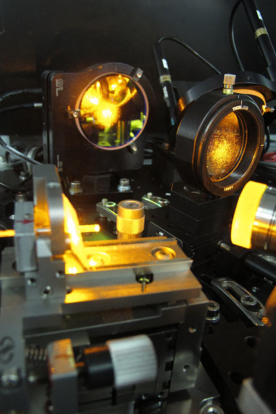
Aligning our Nexstar 11″ with a Hotech CT Collimation ToolOne lesson in high resolution imaging is that collimation matters. Having the optics in your telescope precisely aligned makes all the difference in the results. A small misalignment will result in mushy images that will not quite focus properly. No amount of fancy image processing will salvage the image.
The Nexstar has not been giving me the results I know it is capable of. I shot Venus just before inferior conjunction and noted that there was probably some issues in collimation that were not addressed in the quick star collimation I had performed.
Thus I borrowed a Hotech CT Laser Collimatior from a friend. The collimator is an interesting piece of kit, enabling the user to check more than simple the tip-tilt of the secondary.
Warping is not much fun. Warping is now on my list of responsibilities. At least I know I am accomplishing something critical to the operation of the telescope.
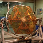
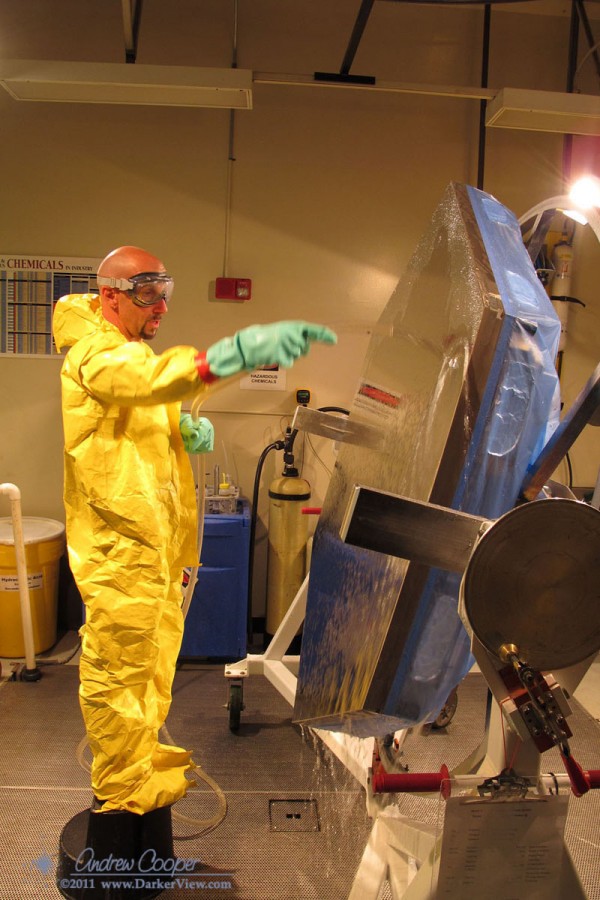
A Keck mirror segment after stripping and cleaning, ready to place in the chamber to receive a new reflective coatingWarping is a process of tuning the performance of a mirror segment after a segment exchange. A segmented mirror offers large advantages over a monolithic mirror, not least of which is the ability to swap a few segments out for re-coating and refurbishment without the weeks of downtime needed to re-coat a monolithic mirror. Throughout the summer Keck schedules a couple days of SegEx each month, so that at the end of the summer we have a completely clean and re-coated mirror.
Exchanging segments does require some interesting procedures to realign each new segment, each must be warped and the edge sensors tuned. The first few hours of the night after a SegEx is used to evaluate the performance of the newly replaced segments. Using a special alignment camera system the optical figure of each segment can be evaluated and a set of corrections generated to be applied the next day… Warping.
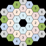
A map of the segment types in the Keck primary mirrorThere are six segment types that make up the primary mirror, each with the slightly different curve needed to make up the correct part of the hyperbolic curve. In theory the segments are interchangeable, any type four can be swapped with any other type four. This works… With a little help. It is necessary to adjust the figure of each segment, just slightly, to tune the figure of each segment for its place in the array.
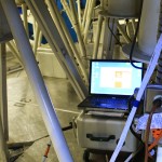
To apply the correct pressure there are small knobs and screws at specific points in the whiffle tree. Each adjustment point also contains a strain gauge, allowing the applied pressure to be measured precisely. A computer and analog interface allows all of the points to be read out and checked against the calculated values.
the warping computer set up in the subcellThere are thirty adjusters and strain gauges on the back of each mirror segment. The problem is that you can not simply adjust each one. Adjustment of one point affects all of the nearby points, particularly if the adjustment is large. Typically it is necessary to go around three times before the segment is properly warped. Thirty adjustments becomes ninety. Three segments in a day becomes 270 knobs to turn, 540 over two days, a lot of knobs.
After setup, it takes about an hour to do each segment, an hour of painstaking frustration. the mirror cell is just the right height, too high to sit down and reach the knobs, too low to stand up fully. Working in a jungle gym of frigid steel just makes it worse. A day in the mirror cell is a nice recipe for a tired and sore body.
How careful was I? Did I get all of the points set correctly? The computer is displaying all of the correct numbers. I will not know until the next day, when the night’s performance data is reduced, when we can see the figure of the primary mirror and check the errors.
My first warp is a success, most of the segments show less than 20nm rms error. Next SegEx there are only two segments being exchanged, but Sergey is threatening to have two others re-warped to address some lingering issues. Four? Better than six. Only 360 adjustments to make, more or less.
It began, as all these things do, with a phone call from Liz…
“It’s stuck”
“What is stuck?”
“SFP won’t move in K2AO.”
“Do not try to move it any further, I am up tomorrow for SegEx, I will go look at it.”
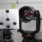
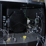
Looking into the partially disassembled side of the Keck 2 AO BenchLast time we tried to free up the SFP stage when it was stuck we carved an L shaped gouge in the cover plate. This is the hazard of optics that move under computer control. We tell the computer to move these optics under the assumption that the encoder position indication is correct, sometimes it is not. In reality there is no way to actually see where the stage is, an optical assembly moving deep within the AO optical bench. For most of the optical stages this is not a problem, if the encoder is not correct you can just reinitialize it and regain the position, the stage can not actually hit anything.
SFP is different, it can crash into the rotator if it gets lost. There is no real way to fix this issue, it has to be this way. SFP stands for Simulator Fiber Positioner, an artificial star created with a optical fiber. Placing the tip of the fiber at the telescope focus creates a bright dot of light that we can use to align and calibrate the AO system. The three axis stage can move the fiber into the light path and accurately position it just where you need it for system tests. There is also a diagonal mirror used to inject light from the telescope simulator and the spectral calibration source mounted atop the simulator.