Over the years I have hand wired so many microcontroller PCB’s. Along with my own projects for myself there are more than a dozen of my little microcontroller devices at work about the observatory. The OSIRIS IR calibration source, the Keck 2 dome inclinometers, a precipitation sensor interface, the Keck 1 AO electronic vault temperature sensors, the weather mast fan and shelter controller, the list goes on. Anyplace a bit of electronic intelligence is needed for the task.
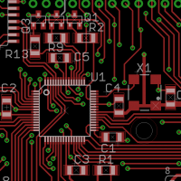
A PCB assembly in layoutOf course the challenge is that each of these controllers has been hand wired and built for a specific task. This takes a few hours of running little wires on a perfboard. And while I enjoy such wiring, it does make the task take notably longer.
While a couple of my microcontroller designs have been laid out on proper circuit cards, like the SciMeasure camera exposure controllers, I have never laid out a general purpose microcontroller PCB. This is not for lack of thinking about it, so many times I have considered this could be so much easier if I could only invest a little time in a layout.
I have been messing about with electronic circuitry for almost four decades. I recently came across an early example of my work. The device is a digital event counter built around classic 74xx series logic. A chain of 74190 decade counters feed a set of 7447 decoder drivers and seven segment LED displays. A plastic project case with switches and connectors reminds me I have been building little devices for a very long time.
A digital event counter built when I was fifteen years old.In some ways the unit is very similar to one of my more recent builds. Perfboard and point-to-point wiring are still standard construction techniques. The technology may have changed across the years, becoming far more complex, but some parts have remained the same.
I am preparing to release a design under the Open Source Hardware Association definition. By releasing a design this way you allow the electronic maker community to freely share and use the design. When following the community rules for open hardware, you can mark your equipment with the open source hardware logo. The logo itself is released under a Creative Commons licence (CC-SA) and is likewise free to copy and use, if you follow the rules.
While the OSHWA website links the logo in KiCAD and several other formats, it does not provide the logo in Eagle format. Off to the web to find an Eagle library with the logo… Hmmm… Found one, but it has issues.
The Open Source Hardware Association logoThere are a couple versions out there on the web. The one most commonly found to was created by NBitWonder. This has a couple issues… While it is very faithful to the official logo it is built from thousands of apertures. Running the CAM processor on it chokes, and chokes hard. While the PCB may take a couple seconds to process the CAM without it, place this logo on the PCB and be prepared to take several minutes to process the CAM. With the NBitWonder version the file sizes grow significantly as you would expect. My GenPIC PCB overlay Gerber file grows from 16kb to over 250kb to accommodate the logo.
I am currently putting the finishing touches on another printed circuit board.
A PCB assembly in layoutLayout of a printed circuit board, or PCB, is one of the most complex puzzles I know. Creating a complex PCB takes a great deal of knowledge, a lot of patience, and a robust set of puzzle solving skills. These are the same sort of puzzle skills that might be used to solve a Sudoku or a tough crossword puzzle. Seeing patterns, spotting errors, trial and error, planning ahead, all skills used to their utmost in laying out a PCB.
A PCB is laid out with specialized software, drawn on the computer screen. The software can then generate CAM files that are sent to a board house, a manufacturer who can take these files and create a physical PCB. The PCB is thin layers of copper etched to create the patterns of traces laminated onto a fiberglass substrate. When designing the PCB each component, each copper conductor, each trace, is carefully positioned by the designer on the screen, dragging objects colored lines about to create a solution.
The golden yellow glow that has dominated the night for generations is disappearing.
Fishing boats under sodium lamps haunt the Tenakee docksLow pressure sodium has been the standard technology for outdoor lighting for generations. the soft yellow glow is familiar to anyone who has lived in any urban area, coloring lives and countless photographs of the night.
The yellow glow of sodium light has been both celebrated and reviled. While the glow can be attractive in night scenery it also creates inhuman tones in faces and photos of people. Movies have been shot under sodium lights, songs reference the golden glow. Astronomers both professional and amateur prefer the lights as the light can be easily filtered from view.
It is always a good day when I drive up the mountain to a broken telescope, then drive down leaving a working telescope. Easy to say, not always easy to accomplish, the simple statement obscuring a day of struggle to solve the problem and fix it.
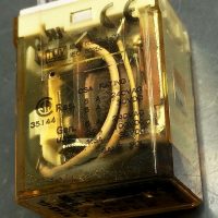
A relay with a blown out coil from the Keck 2 telescope driveSuch a day was Monday.
The Keck 2 telescope drive is a complex beast of dozens of relays, miles of cabling, servo amplifiers and power supplies, plus several circuit boards designed and built in the 1980’s holding a bewildering array of arcane logic.
The Keck Adaptive Optics systems are workhorse scientific instruments. Equipment that has resulted in so many great astronomical discoveries. The AO systems have also seen a great deal of improvements and upgrades through the years. New computers, a new wave-front controller, guide star lasers added, new cameras, different science instruments, and much more.
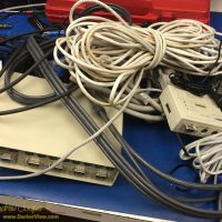
A pile of electronic cruft removed from the Keck 2 AO enclosure.While the new gear has improved the systems dramatically, the result is that there is a fair amount of disused bit and pieces hanging about. Mostly cabling, but more than a few unused boxes of electronic gear are still sitting in place in the racks.
Eventually I just get fed up with it and insist we spend some time getting rid of it. With no AO use scheduled for a while there is a chance to spend a couple days ripping out this pile of cruft. Identifying and removing unused boxes. Following cables to nowhere, wire cutters in hand to snip away the multitude of nylon zip-ties.
We remove three large armloads of cables and other gear, carring the pile down to the electronics lab for sorting through and disposal. Most of it is horribly obsolete, things like KVM’s for PS/2 style mice and keyboards, or cables for old Sun computers. Most of it will simply be thrown out. It feels so good to get it out of AO and to clean up the place a little.
I called this pile of junk cruft, a word that drew funny looks from my co-workers. You don’t know what cruft is? What sort of nerds are you? Sorry, cruft is what I have always called leftover technical junk.
Cruft is jargon for anything that is left over, redundant and getting in the way. It is used particularly for superseded and unused technical and electronic hardware and useless, superfluous or dysfunctional elements in computer software. – Wikipedia
It turns out that the word has a long history in engineering and computer science with a heritage that includes MIT and Harvard. It is indeed the proper word for the detritus that had been accumulating in the AO vault.
I have previously covered the importance of warping, tuning the Keck primary mirror segments for optimum optical performance. Warping has been my responsibility for some years now. Reading out the settings of the thirty strain gauges on the back of each segment is performed by a test fixture, a computer and a sensitive data acquisition system. Over the last year I have designed, built, and programmed a new test fixture.
The old and new warping fixtures being tested side-by-side on a spare segmentThe old warping fixture was showing its age. Built in 2000 it has been in use for 16 years. It is the computer that I was most worried about, it has begun to crash randomly, usually at the worst possible time. Replacing the computer has some issues as well, the A/D system uses a parallel interface, something not found on any modern computer. The operating system is Windows XP, while unsupported, at least you can still install and use this old operating system. The software is in an ancient version of LabView. I have no love for LabView, too many bad experiences with it, it crashes too often and the licensing issues are horrible.
As this is the third generation warping test fixture the name of the software is obvious… Warp3
The tropical environment of Hawaiʻi is not kind to optical instruments. Tropical humidity can cause a host of issues ranging from corrosion of metal parts to decay of wooden and cardboard telescope structures. For those of us who build and use small telescopes the issues of tropical heat and humidity are rather concerning.
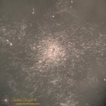
Fungus colony on a small achromatic lens surfaceWorst of all is the fungus. Impressively there are species of fungus that can grow and thrive on clean optical surfaces. It is hard to imaging a more hostile place to grow, seemingly devoid of nutrients and the moisture necessary for life.
I have seen camera lenses lost to the white fungus. A friend once showed me a Canon 70-200 f/2.8 L, a $2000 lens, with fungus covering internal elements. Even on the “dry side” of Waimea the humidity was high enough to allow fungus to destroy this lens.
The problem is not an issue on the summit of Mauna Kea. The high altitude air typically exhibits a relative humidity of less than 10%. Several references note that a humidity of above 70% is needed to promote fungal growth on optics. We see no issues with fungal damage to the mirrors or instruments on the big ‘scopes.
Below the tropical inversion layer (about 6-7k feet) it is another issue entirely. Near sea level, where most of us live, humidity can remain above 80% much of the year. The warm and humid conditions of these islands are idea for growing anything, including the omnipresent fungal gardens that create the smells of a tropical landscape. Fungus is inescapable in this world, the spores drift on the wind and an stay dormant for decades, anywhere conditions are suitable fungus will grow.
The possibility of equipment damage was a major element in our buying a house. Waikoloa is located within one of the driest areas of the island. The humidity typically hovers in the 50’s, dry enough that I have had no issues with the multiple telescopes stored in the garage. Still, I do inspect stored equipment periodically, looking for the dreaded white fungus or other damage wrought by this tropical climate.
It is not a single species of fungus responsible for the problem. Apparently quite a few species are able to colonize an optical surface. Looking through the literature I find referenced to multiple species that can grow on optical glass…
The fungi which grow in optical instruments belong to the groups Phycomycetes, Ascomycetes and Fungi Imperfecti. The following species were frequently isolated from instruments which had been in New Guinea: Penicillium spinulosum, Thom.; P. commune, Thom.; P. citrinum, Thom.; Aspergillus niger, Van Tiegh.; Trichoderma viride, Pers. ex-Fr.; Mucor racemosus, Fres.; and M. ramannianus, A. Moeller. So far, Monilia crassa has not been isolated from Australian instruments, although Dr. W. G. Hutchinson (5) of the United States, found this to be a common species in the Panama zone, and it has also been recorded as frequent in West Africa by Major I. G. Campbell. – J.S. Turner, et al.1
I admit that the fungus can be pretty, in an odd sort of way considering the damage. Under a microscope it appears lacy, the mycelium fibrils growing across the glass in search of more nutrients to support the colony. In the center small round fruiting bodies are the launching point for new fungal spores.
I recently had another round of battle with fungus while restoring a collection of instruments that had been stored in a garage on the side of Hualalai. The high humidity had wrought impressive damage on both the optics and metal components of the telescopes. And there is fungus! Found in the eyepieces and on the telescope mirrors. During the cleaning and restoration of the instruments I found it necessary to completely dismantle many optical assemblies just to remove and kill the fungus. I some cases I was in time, but not completely, it is not without regret that I throw a $400 eyepiece into the trash.
Dealing with the fungus is imperative, cleaning and killing the growth before severe damage can be done may save the equipment. If the growth is severe enough the glass surface and the coatings can be damaged. Apparently the fungi can excrete hydrochloric acid, etching the surface and creating permanent damage.
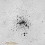
Fungus colony on a small achromatic lens surfaceMinor damage may not be enough to ruin the device. It actually takes a great deal of damage to appreciably affect the performance of most optics. A few small specks of damage remaining on the surface after cleaning may not be noticeable. Inspection of each spot of damage with a microscope can be useful, Sometimes it is clearly damage of the surface and irrepairable. I have also found hard deposits that at first glance appeared to be damage under the core of fungal colonies that remained after cleaning. These may be removed using a soft wooden tool like a toothpick or chopstick.
Killing the fungi requires a solvent that will both kill the fungus while not damaging the optical surface. I find references to both alcohol as well as other solvents. A mix of 50/50 hydrogen peroxide and ammonia is recommended by some references. Along with cleaning the glass I am careful to soak all of the structural elements as well. The tube, the spacers and lock-rings can all harbor minuscule colonies or spores awaiting suitable conditions to grow again.
Optical fungicide solutions tend to be expensive and hard to obtain, but they are available from some optical equipment manufacturers. Alternatively, you can use a 50/50 mix of hydrogen peroxide (H2O2) and ammonia (NH3). Usually, 5 ml of each is adequate (10 cc in total). Mix just prior to use and do not store the mixed product. – Ismael Cordero, Community Eye Health Journal2
Living in a warm humid environment one must be vigilant and ready to deal with issues when found. Examine optics regularly, keep a can of WD-40 next to the tool box (and use it), store optics and electronics with plenty of ventilation and reduce the humidity to well below 70% if needed. Extra vigilance to preserve valuable equipment is the price of living in paradise.
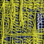
I am no stranger to point-to-pointwiring. I routinely use the technique to build small circuit boards. Well done point-to-point is a permanent and reliable way to build a complex electronic device.
Welded point-to-point wiring on a complex circuit board
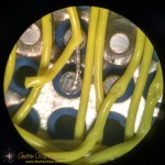
But then there is this circuit board assembly I came across… At first glance it looks like a wire wrap board. But there are no posts, the wires are flush to the board. Neither is it traditional point-to-point wiring, the wires are not terminated to solder pads beside the pins being connected. I had never seen a construction technique like this.
The board is an old PCB assembly found in a storage cabinet while clearing out the old junk that has accumulated about the observatory. No idea where it came from or what it was used for, the only clue is some writing on the box… “Keck level shifter”, Perhaps a piece of a detector controller? Someone clearly put a lot of work into the board at one time, now it sits in my office as unknown junk. It is the odd construction technique that caught my eye and led me to hang on to the board, at least temporarily. What is this?
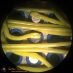
A closer look under a microscope shows a connection clearly made by some sort of spot welder. There is a neat little hole through the insulation at each connection. Stripping back the insulation reveals a very neatly welded wire. Each wire is welded to the flat bottom of each pin socket. Every component pin is socketed, this includes all passives, which are mounted to headers and plugged in alongside the IC’s.
There are a number of advantages to this wiring method… The connections should be very reliable and robust, the weld is a nearly ideal electrical connection. As no connection pads are needed beside each socket the density is much higher using less circuit board real estate per component, you can cram more on the board. Interestingly the connection technique can be used without terminating the wire, daisy chaining to the next connection point.
There are disadvantages as well… The method clearly requires some sort of welding equipment with perhaps an automatic wire feeder and cutter, a built-in microscope for positioning the weld, and more. Clearly an expensive piece of kit. No components can be present during welding as they may suffer damage from the high electrical currents needed for spot welding, thus everything must be socketed. All those little sockets are expensive! Rework or repair would need to be done with more traditional soldering techniques.
I would love to see the machine that did this board assembly. Maybe even a chance to use it. More information on the process seems difficult to find on the web without a trade name or other keyword that would clearly identify the process.
Not that these welded wires would be of much use today. The technique is clearly ideal for complex digital circuits of the style and speed that was common through the 1980’s to around 2000 or so. After that the prevalence of surface mount technology and the abandonment of the DIP package would doom the method. Modern high speed circuits benefit greatly from the more controlled traces of a printed circuit board and would not fare well on a welded wire board. In these days of easy computer layout and cheap printed circuit boards welding would not be my fabrication method of choice.
Welded point-to-point wiring on a complex circuit board
Detail of a connection in welded point-to-point wiring on a complex circuit board
Detail of a weld in welded point-to-point wiring on a complex circuit board
Component side of a welded point-to-point circuit asembly