I have previously covered the importance of warping, tuning the Keck primary mirror segments for optimum optical performance. Warping has been my responsibility for some years now. Reading out the settings of the thirty strain gauges on the back of each segment is performed by a test fixture, a computer and a sensitive data acquisition system. Over the last year I have designed, built, and programmed a new test fixture.
The old and new warping fixtures being tested side-by-side on a spare segmentThe old warping fixture was showing its age. Built in 2000 it has been in use for 16 years. It is the computer that I was most worried about, it has begun to crash randomly, usually at the worst possible time. Replacing the computer has some issues as well, the A/D system uses a parallel interface, something not found on any modern computer. The operating system is Windows XP, while unsupported, at least you can still install and use this old operating system. The software is in an ancient version of LabView. I have no love for LabView, too many bad experiences with it, it crashes too often and the licensing issues are horrible.
As this is the third generation warping test fixture the name of the software is obvious… Warp3
The tropical environment of Hawaiʻi is not kind to optical instruments. Tropical humidity can cause a host of issues ranging from corrosion of metal parts to decay of wooden and cardboard telescope structures. For those of us who build and use small telescopes the issues of tropical heat and humidity are rather concerning.
Fungus colony on a small achromatic lens surfaceWorst of all is the fungus. Impressively there are species of fungus that can grow and thrive on clean optical surfaces. It is hard to imaging a more hostile place to grow, seemingly devoid of nutrients and the moisture necessary for life.
I have seen camera lenses lost to the white fungus. A friend once showed me a Canon 70-200 f/2.8 L, a $2000 lens, with fungus covering internal elements. Even on the “dry side” of Waimea the humidity was high enough to allow fungus to destroy this lens.
The problem is not an issue on the summit of Mauna Kea. The high altitude air typically exhibits a relative humidity of less than 10%. Several references note that a humidity of above 70% is needed to promote fungal growth on optics. We see no issues with fungal damage to the mirrors or instruments on the big ‘scopes.
Below the tropical inversion layer (about 6-7k feet) it is another issue entirely. Near sea level, where most of us live, humidity can remain above 80% much of the year. The warm and humid conditions of these islands are idea for growing anything, including the omnipresent fungal gardens that create the smells of a tropical landscape. Fungus is inescapable in this world, the spores drift on the wind and an stay dormant for decades, anywhere conditions are suitable fungus will grow.
The possibility of equipment damage was a major element in our buying a house. Waikoloa is located within one of the driest areas of the island. The humidity typically hovers in the 50’s, dry enough that I have had no issues with the multiple telescopes stored in the garage. Still, I do inspect stored equipment periodically, looking for the dreaded white fungus or other damage wrought by this tropical climate.
It is not a single species of fungus responsible for the problem. Apparently quite a few species are able to colonize an optical surface. Looking through the literature I find referenced to multiple species that can grow on optical glass…
The fungi which grow in optical instruments belong to the groups Phycomycetes, Ascomycetes and Fungi Imperfecti. The following species were frequently isolated from instruments which had been in New Guinea: Penicillium spinulosum, Thom.; P. commune, Thom.; P. citrinum, Thom.; Aspergillus niger, Van Tiegh.; Trichoderma viride, Pers. ex-Fr.; Mucor racemosus, Fres.; and M. ramannianus, A. Moeller. So far, Monilia crassa has not been isolated from Australian instruments, although Dr. W. G. Hutchinson (5) of the United States, found this to be a common species in the Panama zone, and it has also been recorded as frequent in West Africa by Major I. G. Campbell. – J.S. Turner, et al.1
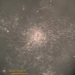
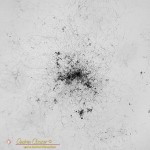
I admit that the fungus can be pretty, in an odd sort of way considering the damage. Under a microscope it appears lacy, the mycelium fibrils growing across the glass in search of more nutrients to support the colony. In the center small round fruiting bodies are the launching point for new fungal spores.
I recently had another round of battle with fungus while restoring a collection of instruments that had been stored in a garage on the side of Hualalai. The high humidity had wrought impressive damage on both the optics and metal components of the telescopes. And there is fungus! Found in the eyepieces and on the telescope mirrors. During the cleaning and restoration of the instruments I found it necessary to completely dismantle many optical assemblies just to remove and kill the fungus. I some cases I was in time, but not completely, it is not without regret that I throw a $400 eyepiece into the trash.
Dealing with the fungus is imperative, cleaning and killing the growth before severe damage can be done may save the equipment. If the growth is severe enough the glass surface and the coatings can be damaged. Apparently the fungi can excrete hydrochloric acid, etching the surface and creating permanent damage.
Fungus colony on a small achromatic lens surfaceMinor damage may not be enough to ruin the device. It actually takes a great deal of damage to appreciably affect the performance of most optics. A few small specks of damage remaining on the surface after cleaning may not be noticeable. Inspection of each spot of damage with a microscope can be useful, Sometimes it is clearly damage of the surface and irrepairable. I have also found hard deposits that at first glance appeared to be damage under the core of fungal colonies that remained after cleaning. These may be removed using a soft wooden tool like a toothpick or chopstick.
Killing the fungi requires a solvent that will both kill the fungus while not damaging the optical surface. I find references to both alcohol as well as other solvents. A mix of 50/50 hydrogen peroxide and ammonia is recommended by some references. Along with cleaning the glass I am careful to soak all of the structural elements as well. The tube, the spacers and lock-rings can all harbor minuscule colonies or spores awaiting suitable conditions to grow again.
Optical fungicide solutions tend to be expensive and hard to obtain, but they are available from some optical equipment manufacturers. Alternatively, you can use a 50/50 mix of hydrogen peroxide (H2O2) and ammonia (NH3). Usually, 5 ml of each is adequate (10 cc in total). Mix just prior to use and do not store the mixed product. – Ismael Cordero, Community Eye Health Journal2
Living in a warm humid environment one must be vigilant and ready to deal with issues when found. Examine optics regularly, keep a can of WD-40 next to the tool box (and use it), store optics and electronics with plenty of ventilation and reduce the humidity to well below 70% if needed. Extra vigilance to preserve valuable equipment is the price of living in paradise.
I am no stranger to point-to-pointwiring. I routinely use the technique to build small circuit boards. Well done point-to-point is a permanent and reliable way to build a complex electronic device.
Welded point-to-point wiring on a complex circuit board
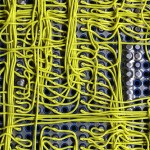
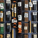
But then there is this circuit board assembly I came across… At first glance it looks like a wire wrap board. But there are no posts, the wires are flush to the board. Neither is it traditional point-to-point wiring, the wires are not terminated to solder pads beside the pins being connected. I had never seen a construction technique like this.
The board is an old PCB assembly found in a storage cabinet while clearing out the old junk that has accumulated about the observatory. No idea where it came from or what it was used for, the only clue is some writing on the box… “Keck level shifter”, Perhaps a piece of a detector controller? Someone clearly put a lot of work into the board at one time, now it sits in my office as unknown junk. It is the odd construction technique that caught my eye and led me to hang on to the board, at least temporarily. What is this?
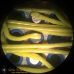
A closer look under a microscope shows a connection clearly made by some sort of spot welder. There is a neat little hole through the insulation at each connection. Stripping back the insulation reveals a very neatly welded wire. Each wire is welded to the flat bottom of each pin socket. Every component pin is socketed, this includes all passives, which are mounted to headers and plugged in alongside the IC’s.
There are a number of advantages to this wiring method… The connections should be very reliable and robust, the weld is a nearly ideal electrical connection. As no connection pads are needed beside each socket the density is much higher using less circuit board real estate per component, you can cram more on the board. Interestingly the connection technique can be used without terminating the wire, daisy chaining to the next connection point.
There are disadvantages as well… The method clearly requires some sort of welding equipment with perhaps an automatic wire feeder and cutter, a built-in microscope for positioning the weld, and more. Clearly an expensive piece of kit. No components can be present during welding as they may suffer damage from the high electrical currents needed for spot welding, thus everything must be socketed. All those little sockets are expensive! Rework or repair would need to be done with more traditional soldering techniques.
I would love to see the machine that did this board assembly. Maybe even a chance to use it. More information on the process seems difficult to find on the web without a trade name or other keyword that would clearly identify the process.
Not that these welded wires would be of much use today. The technique is clearly ideal for complex digital circuits of the style and speed that was common through the 1980’s to around 2000 or so. After that the prevalence of surface mount technology and the abandonment of the DIP package would doom the method. Modern high speed circuits benefit greatly from the more controlled traces of a printed circuit board and would not fare well on a welded wire board. In these days of easy computer layout and cheap printed circuit boards welding would not be my fabrication method of choice.
Welded point-to-point wiring on a complex circuit board
Detail of a connection in welded point-to-point wiring on a complex circuit board
Detail of a weld in welded point-to-point wiring on a complex circuit board
Component side of a welded point-to-point circuit asembly
My slide digitizing project is now producing data by the gigabyte. As expected I am filling up the drives on my desktop computer. Not that there was a lot of space available in the first place, less than 50Gb was clear on the primary data drive. Time to buy a new hard drive! At least when I built the computer I bought a gaming cabinet with plenty of drive bays.
The hard drives of my desktop computer, Darker View is in there somewhere.I face the agonizing decision… When dealing with critical data, what brand and model of hard drive do I buy? I make multiple copies, but still, a failure can cost me days of work between backups. What hard drive do I buy for my photos?
The reviews on Amazon and other retailers are nearly useless on hard drives. There will always be failures of devices like this, and angry buyers are very likely to leave negative reviews. Thus the data looks very skewed and it is hard to evaluate the reliability in any sort on meaningful way. Much less compare one drive to another.
There is real data! The cloud storage provider BackBlaze runs thousands upon thousands of hard drives. Obviously hard drive failure rates are of paramount importance to them and they closely track each type of drive they buy. Fortunately for the rest of us they publish this data and allow us to see what does, and does not work.
There are several obvious lessons in the data… Stay away from the 3Tb drive from Seagate and to a lesser extent the 3Tb drives from Western Digital. Several 4Tb models appear to be far more reliable. The failure rates on the worst drives can be upwards of 20% to 30% per year, while the better drives well under 5%. Those rates may seem high, you need to consider the hard use these drives get in a data center.
Based on this I have a new HGST 4Tb drive installed in my computer. All looks good so far, a trouble free installation and my photo collection copied over without issue. Now to see how long the drive lasts when I put some hours on it.
Getting rain or snow on the primary mirrors is bad.
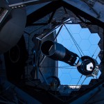
The Keck 2 primary mirrorThe normal method of detecting conditions that might lead to rain or snow is by monitoring the humidity or dew point. If the dew point approaches the current temperature, to within a few degrees the operators must close the domes. This is much the same thing as the humidity approaching 100%. Thus I have installed several new humidity/dew point/temperature sensors over the last few years. These replaced some old and troublesome equipment that had been in place for over a decade.
The problem… You can have both rain and snow occur with low humidity. Moist air above the telescope can produce rain or snow which falls into drier air at the summit level. This can catch the operators by surprise, a situation we have observed on a number of occasions.
To help detect this you can deploy a precipitation sensor, something some of the neighboring telescopes have done. The engineers over at CFHT were kind enough to show me the units they had installed during their remote operation project.
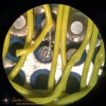
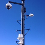
Various instruments atop the Keck Observatory weather mastYes, I just went out and bought one. Not just any old unit either… The best precipitation sensor I could locate on the market, a Vaisala DRD11A. The sensor uses a capacitive detection method. Moisture on the top of a plate will change the capacitance and trigger the sensor. The plate is tilted to allow rain to run off and heated to melt snowflakes and sleet. testing on my work bench showed this to be pretty effective and quite sensitive. Yes, you can visualize me sitting at the bench dripping water on a sensor… It worked.
Not that the project was finished there… The new sensor does not come with any sort of network interface. Rather surprising given that just about everything else Vaisala sells has either a serial interface or an ethernet interface. This sensor has just a couple simple outputs… A logic level indication of precipitation, an analog output representing roughly how much, and a frequency output representing the same thing. I needed to interface this unit to the network. As I have installed a terminal server in the rack below the weather mast, at the minimum I needed a serial port.
While I was at it there are a couple other little devices I want to install on the weather mast. These need a network interface as well. May as well put together another little PIC controller and assemble it all together in one neat little package. a few evenings of coding and I had my solution, an interface that allowed remote computer control and status read-back. How many microcontrollers do I have performing little tasks at the summit now? Quite a few.
It may be the day after Thansgiving, but that did not stop the electrical contractors installing new streetlamps in Waikoloa Village.
The electrical contractors show off the new LED lights for our neighborhoodWe noticed the truck and crane setup mid-morning under the light across the street from our house. It was no surprise, the streetlights have been getting changed throughout the neighborhood over the last couple months. The new LED lamps are far better, with almost no glare seen from the side.
We are not sad to see the old low pressure sodium light go, it has been a nuisance. The poorly designed sodium lamp creating glare into our windows We had called to complain with the county, but nothing was ever done. The glare intruded on our bedroom window, a real issue, somewhat alleviated by the growth of our plumeria along the front blocking the light, a deliberate solution on my part.
The big question is whether the new LED light improves the astronomy situation from my driveway. The old sodium lamps along the street made it impossible to do visual observing, there was simply too much glare. The new lamps should darken the sky and create far less light directed at my driveway.
Even better, the lamps in question are C&W Energy Star Friendly® units with reduced blue emissions. Elimination of almost all of the blue light greatly reduces scatter in the atmosphere and is better for the observatories.
The view down the street from the driveway with the new LED lampsThis seems to be the case. I can see the light from our driveway where it is strong enough to cast shadows. Still, it is much darker than it was with the sodium lamps. The overall amount of light is way down, indeed the entire neighborhood is darker.
With the old light I was able to do astrophotography from the driveway using an LPR filter that blocked the 589nm of sodium light. The new lights will have a broader spectrum and be more difficult to block. On the other hand they send very little light upwards, possibly improving the situation. It will be interesting to see what the difference is. When the Moon is a few days further gone I will have to setup the camera and find out.
It may also be a good idea to check the old CloudCam images against new images as the replacement continues. It will be interesting to see if the emissions from the neighborhood are effectively reduced as seen from the top of the mountain.
As I teenager I taught myself digital electronics. Working from the classic books of the day, mostly the TTL Cookbook, I built a succession of projects. Among these was my first clock. Unlike other projects, this clock was a kit from Jameco Electronics. It actually had a printed circuit board, a wooden case, and a red acrylic face. Not only did I get to solder a real circuit board for the first time, I learned every gate and flip-flop in the circuit. When I finished I knew how it worked.
A GPS observing clock or a bomb?I have built a few more clocks over the years, sometimes with classic seven segment LED displays. The latest was a GPS clock built in the 1990’s to provide accurate time on my observing table beside the telescope in the night. To a nerd like me the glowing LED displays are simply cool, something about this red glow contains a quality missing in the slick color LCD display of my modern phone or tablet computer.
On Monday this week a teenage high school student was arrested and interrogated by police for bringing a digital clock of his own construction to school. Like any young budding engineer Ahmed Mohamed wanted to show off his creation. Unfortunately the closed minds of MacArthur High School in Irvine Texas only saw a Muslim student with a possible bomb. It is clear someone has been watching way too much Fox News.
The most poignant part to me is Ahmed being led out of the school in handcuffs wearing a NASA t-shirt. In those photos I saw myself, a nerd in High School, doing the same things, starting on a road that would eventually lead me to an engineering job on the world’s most powerful telescopes.
A digital clock built by Ahmed Mohamed, photo released by the Irvine Texas police departmentFortunately the nationwide condemnation of the school administration and local police force has been swift and unforgiving. Social media has seized on this incident, the school’s Facebook page roiling with sharp criticism. Nationwide press articles have been equally unforgiving. Tech industry celebrities like Facebook’s Mark Zuckerberg have shown their support. Ahmed has even received a tweet and an invitation from the president…
Cool clock, Ahmed. Want to bring it to the White House? We should inspire more kids like you to like science. It’s what makes America great. – Tweet by President Barack Obama
It is gratifying to see that the message of many of these comments is that a young person building an electronic project is something to be celebrated, not feared. We should be encouraging students to experiment, to build, to learn. True engineers start this way, exploring technology for themselves, the experience gained can not be taught in a classroom. In my career I have met and worked closely with dozens of engineers, I can tell which ones were tinkerers and makers before they started college, who build and create for the sheer joy of it.
Ahmed is not sure if he will return to school immediately and the family is consulting with attorneys. Police are currently holding the clock as evidence. Thirty years later I still have my first clock.
A small box with my name upon it, sitting on the shelf in our shipping department for me to pick up. The procedure is simple… Grab the box and note your receipt on the clipboard hanging at the end of the shelf.
A ribbon cable, one of three in a shipment.I have been awaiting this shipment for a while now, hoping to continue a project to build a new test fixture. But the shipment is not complete. The latest box contains three little bags, not what I am really hoping for.
What is it this time? I open the box, open one bag, take out the anitstatic bag within that and find… A ribbon cable.
I just have to sit back and stare at this in sheer disbelief.
The disbelief has been building for a week now as the boxes have appeared in our shipping department one by one. A single order, a pair of A/D units and accessories. I have now received four separate boxes, all delivered FedEx, and not received the actual A/D systems themselves, only the various accessories.
One box with three double bagged ribbon cables that weigh all of a few ounces each and are ten inches long. All of the accessories I have received in the four boxes could easily have fit in one box. The anti-static bag is even more unbelievable. These metallized mylar bags are not cheap. Why would you put one around a component that is totally immune to static damage? A ribbon cable with connectors at each end? To be static sensitive it would have to at least contain a semiconductor component of some sort. One transistor? Then you seal a poly bag around that? At least it was brown paper and not foam peanuts used to fill the rest of the box.
With this order National Instruments has by far topped the worst overpackaging I have seen to date. Quite something in the electronics industry where overpackaging is the norm. It used to be Digikey was the worst I had ever seen, but they have gotten much better over the last few years, shifting to all brown paper packaging aside from the plastic bag around the parts themselves.
How is it even possible to receive a small order in four separate FedEx shipments and not even get the primary thing you ordered? To Hawaiʻi? How can you construct a shipping system that inefficient and make any profit after paying the shipping bills? It is not like any of the accessories do me any good without the main units, no need to rush them. One box with everything would be quite acceptable.
Today will be 86,401 seconds long. That number may seem odd, particularly when you consider that most days are 86,400 seconds long. The difference is a result of the leap second being added to our clocks at the end of June 30, 2015 at 23:59:59.
Two new GPS time servers installed in the Keck 2 computer roomThe need for an extra second comes from the irregular rotation of our planet. Due to gravitational interaction with the Moon our planet is gradually slowing its rotation. Other shifts can also cause slight irregularities in the planetary rotational rate. In order to keep Coordinated Universal Time in phase with the Earth’s rotation it is necessary to insert an extra second every so often when the error becomes too large.
Since zero hours universal time occurs at 14:00 Hawaii Standard Time, this extra second will occur at 2pm in the afternoon for my readers in the islands. If you are watching a clock that can account for this leap second you will see this second appear. The clock can do a few things, it could simply stop for a second, holding at 23:59:59 for two seconds. The clock could also count the extra second, displaying 23:59:60.
Update: A small group of true nerds gathered in the Keck 2 computer room at 0hUT today and watched our timeserver do leap second. The display notably remained at 23:59:59 for two seconds.
Generally only high precision time servers and GPS receivers will contain software to correctly implement the leap second. Most clocks do not correct for leap seconds, it is just not that important that this feature be implemented perfectly in most devices.
Network connected clocks will simply adjust the time on the next opportunity. Connected clocks routinely synchronize with an online time standard. Your computer requests the correct time via NTP protocol from an internet time server once each day, this is the usual default configuration for a net connected computer unless you have changed it. Cell phones get their time from the network and may receive their extra second more quickly, maybe within a few moments of the leap.
The rest of the clocks in your life are usually more than a few seconds off in any case.
Last time this occurred in 2012 there were some troubling software crashes around the world. Airline departures were delayed and some major websites went down. There is some concern that similar occurrences may occur this time. As a result some experts have argued to do away with leap seconds and just let the error accumulate. The argument rages and we may see leap-seconds abolished, in the meantime this one will occur.
Now that you know about it, enjoy your extra second today. Remember to watch that clock at zero hours universal time and see what happens.
The Keck 1 dome lit by the glow of sunsetI pressed the button.
It moved.
700 tons of steel and aluminum smoothly rotated until I hit the stop button.
Nothing crashed or seriously broken.
It even moved the right direction.
The risk of breaking something was a real possibility. A mistake here could leave the dome damaged for days or weeks and the telescope useless. I reviewed my plan one more time before starting. A fully written plan with a step by step testing method carefully thought out and reviewed by the other engineers in the department. The plan also had a whole section of “what can go wrong” risk analysis, with risk mitigation steps. What if the brakes release but the motors do not come on? What if the old controller fails when removed from the system?
After a fitful night’s sleep and a long ride to the summit the moment came when I brought the new controller online. Swapping out the connections with the old controller and applying power, the correct indicator lights came on. Even better, as I tested each of the controls in turn the dome and shutters operated perfectly. It worked from the control panel, from the radio controller, under computer mode from the control room. I even tracked the telescope and dome together for an hour without trouble. The tracking was excellent, within 0.1° the whole time.