
In April 2001 I realized a dream that had been many years in the dreaming and a year in the making, a large aperture dobsonian.

- The scope had to have sufficient aperture to take advantage of the dark skies available near Tucson. I wanted to see spiral arms in galaxies.
- The design was to be visual only. No drives, but provisions for an equatorial platform at a later date.
- The mount would be a no compromise rigid structure, capable of allowing good optics to perform at their best.
- The scope had to fit through a standard doorway.
- The scope had to fit in the cargo compartment of a Ford Explorer Sport without dropping the seat for safety during transport.
- The eyepiece must not be an excessive distance above the ground, allowing use while standing on the ground much of the time. (But then, I’m 6’2″ tall)
Over a decade of engineering experience has taught me that a well defined set of specifications can make all the difference at the end of a project. With these design goals in mind the plan then progressed rapidly.
The Primary
The heart of any telescope is the primary mirror. The primary started life as a cast pyrex blank from Newport Glass, ordered for $550. Purchased with f/4.5 curve generated and a blanchard ground backside. A polarized light test showed no visible stresses.
His price for the mirror… a second 18″ frame.
I delivered the blank to Tom and received a finished mirror six months later. Under an interferometer it showed a smooth 1/16th wave surface. Star testing shows no obvious defects. A coating applied by Spectrum Coatings and I have a beautiful primary. The second frame was completed a couple years later when Tom purchased an 18″ blank of his own.
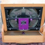
The Mirror Cell
The mirror cell is an 18 point flotation design built to the specifications from Berry and Kreige. The only departure is in the design of the strap.
The 1″ wide spreaders were done to the dimensions given in Berry and Kriege. I have decided that they are too narrow. Mine had begun to bend under the weight of the primary, especially during transport. These have been replaced with wide aluminum spreaders.

The collimation bolt interference could be easily solved by arranging the bolts with the two bolts on the lower rung, this would allow the rocker box to be roughly 2cm (1 inch) shorter and more compact. This would also lower the eyepiece an equal distance closer to the ground. The spacing of the rungs and other dimensions would have to be changed to do this.
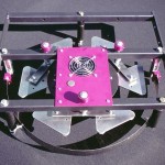
With the cell turned over you can see the cooling fan and the collomation bolts. With more of the violet anodized aluminum that gives the scope its name.
The strap is a piece of beryllium copper alloy surplused from an engineering project I worked on. It was intended for stamp forming of battery charger contacts. It is very flexible, has little thermal mass as it is only 0.020in. thick and does not stretch.

The end result is a mirror cell that holds the mirror with no visible distortion. I have star tested the telescope and any flexing of the mirror should have been visible, but none is seen. I am going to attempt to photograph the defocused star images. The plan is to use polaris to overcome the lack of a drive.
As of Sep 2002 I had solved (at least for now) the problem of the bending spreader bars by taking the set from the second mirror cell and doubling them up with the old ones. At the same time flipping the old ones over so that the bend was upwards. New wide aluminum spreaders have been manufactured for both scopes.
I also cut the lower collimation bolt 1cm shorter while I had everything apart. It no longer interferes with the azimuth encoder.
The Mirror Box
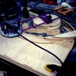
Shown to the right is the mirror box just after assembly, with some of the clamps removed. All of the wooden assemblies are manufactured from Appleply. Expensive and hard to find, this wood is great to work with.
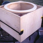
Shown here is the gusset gluing operation. The gussets are made from scraps of the same wood as the box. They were carefully mitered on a table saw with a custom made jig to get the 45 degree angle to the edges. The hope is that using gussets to reinforce the corners, there would be no racking of the mirror box, that it will remain perfectly square under load.
All of the glue used was a waterproof wood glue. This is in keeping with the goal of making a telescope immune to dew and maybe even rain. Exposure to moisture is all too possible with a telescope used outdoors. All glues waterproof, almost all the hardware is stainless steel, the machined aluminum parts were anodized, all of the wood was liberally treated with an oil stain/preservative before being coated with multiple layers of polyurethane.
Update: After ten years of use, being heavily covered in dew many times to the point of drips running down the side, even one thunderstorm downpour, there is no moisture damage apparent.
The Rocker Box
When I reviewed the design of the rocker box I realized two attributes were important. The box must be accurately made, the four elevation pads held squarely to the lower surface, and the assembly must be very stiff.
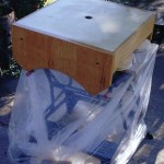
The photo above shows the fully assembled rocker box with the last coat of polyurethane drying on the patio. Warm Arizona spring days made for quick drying times of the thin sprayed coats.
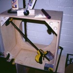
The Pivot
One aspect of the design I put some design effort into improving was the azimuth rotation pivot. I realized that if this heavy scope was to be used on an equatorial platform that a great deal of sideways load would be placed on the pivot. This called for a heavier assembly than some designs I had seen.


The end of the pivot is prepared to receive the azimuth encoder by drilling a hole in the end of the shaft to receive the encoder shaft.
The Ground Board
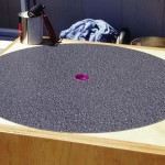
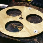
The completed ground board can be seen in the photo to the right. Teflon pads and the azimuth pivot are installed. Also seen are the large circular cutouts used to reduce the weight here. This is possible as the ground board serves only one purpose, to hold the azimuth pads and feet in the correct place.
Update: After many years it has never been desirable to improve the feet, these are stil the simple solid wood feet the telescope was originally equipped with.
The Secondary Cage
The business end of the scope, the secondary cage is built as light as possible to allow the scope to balance near the rear. I used the traditional design, two high grade plywood rings held apart by aluminum struts and a sheet of kydex plastic to block the light.
I added a machined aluminum ring over the knob of the focuser to expand the knob size and make it much more finger friendly.
Update: The Astrosystems phase IV was a decent focuser, but the Feathertouch is better! The Phase IV was replaced in 2004 with a Feathertouch, a very nice improvement.
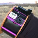
Digital Setting Circles
Finding one’s way about the sky can be a challenge. I am a bit of a purist when it comes to this issue. I believe that to learn the sky properly no finding aids should be used. I often star hop and for a Messier Marathon I use nothing but charts and a Telrad.
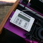
After talking to may other large dob users I decided to get the Sky Commander unit. Good choice! The unit is easy to use and very accurate. On my first night using the unit to track down Herschel 400 objects the sky commander would routinely place an object dead center in a 20 arcmin field allowing me to find and record over 35 objects in a single short summer night. No time was spent hunting for the objects. This says a great deal about the accuracy of the telescope mount. If you have a well build dobsonian with truly orthogonal azimuth and elevation axis a set of DSC’s will work well.
I did order the 2048 step encoders from US Digital, with 4 phase quadrature these encoders give 8192 steps of resolution, or 2.6 arcmin. Easily enough to put the target in the field of a high power eyepiece.
 |
 |
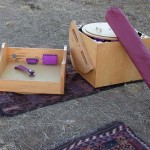
Setup
Transporting a big dob and setting it up is where the use of a telescope this size becomes a serious commitment. Setup and takedown are about 10-15min, add in the need to collimate the scope each time. This, of course, becomes smoother with practice and the development of routine. Finding where to put everything, how to pack the scope and ancillary equipment in the vehicle. All of the trivia that we who regularly use portable scopes require to make this task reasonable.
Final setup clamping the secondary cage in place
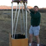
The truss tubes are then clamped into the mirror box and the secondary cage is set on top and clamped into position. The scope is stable through this operation as it is back heavy and tends to point straight up. Once the secondary cage is in place the scope is close enough to balance to be moved to any needed position for installation of the shroud, encoders and finder.
The mirror cover is left in place until everything is assembled to protect the primary from the many things that could easily fall on it.
The final touches are pulling the shroud into place and setting up the encoders. The arm for the elevation encoder fits quickly into place with two 1/4″-20 cap screws that thread into brass inserts into the side of the rocker box.
These photos were taken while setting up at Las Cienegas for a wonderful night with many others of the TAAA on 12 Jan 2002.
 |
 |
 |
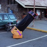
As mentioned above part of the challenge is to pack it all neatly in the vehicle. Part of this was by design and part just worked out with experience. One design specification was for the scope was to fit into the back of a two door Ford Explorer without dropping the rear seats, this was achieved. Some of the chance elements; finding a ladder that fits along the side of the vehicle neatly, that the other basic gear, eyepiece case, accessory case and library, stack neatly in the remainder of the cargo compartment.
First Light!
First light was achieved atop Kitt Peak, Arizona. TAAA’s spring Star-B-Que atop the mountain gave me an opportunity to set up the scope under the stars for the first time. My traditional first light target is M42 and this was no exception. 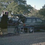
Having the ‘scope work so well first time out was a tremendous relief. All of the work, hours of sweating over every little detail. To see the image for the first time was the culmination of all that effort.
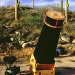
Desert observing
An early outing of the telescope to a desert site sees the ‘scope set up among the Saguaros of the Tortillita Mts. A number of issues had not yet been resolved, but the process is well underway… The new elevation bearings are installed as well as the encoders. The Sky Commander had not yet arrived, thus operation is completely manual.
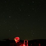
Desert Star Party
At this point the scope is still seeing heavy use almost three years after completion. Deep Violet has been a joy to observe with, performance is as good or better than any scope I have ever seen in her class.
On the night this photo was taken I stopped by M33 expecting to spend a minute or two looking at a galaxy I had seen so many times before. Surprised might be too pale a word to describe my reaction. Spiral arms, HII star forming regions, structure everywhere that smaller ‘scopes show a mere haze. I spent the next hour exploring the galaxy, matching features with the charts.
24 Oct 2003 Farnsworth Ranch, Pima Co., AZ
46cm f/4.5 Deep Violet
Fantastic! A large diffuse object with a large core, some structure visible at 60x with averted vision, at 175x much of the structure is obvious, particularly the main arms extending north-south from the core and several HII regions with separate designations NGC588, NGC592, NGC595, NGC604, as well as IC137 and IC143, on the whole a sublime and complex scene, a whole new galaxy with the 18
There have been some modifications at this point, a new diagonal mirror and the replacement of the first stage spreaders in the mirror cell when the originals started to bend. The replacement were manufactured from 0.35″ aluminum and anodized… violet.
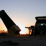
Las Cienegas
A memorable outing with violet set up at Las Cienegas early Thanksgiving morning enjoying a crisp Arizonan fall sky. Violet is still regularly used five years after completion. A few dings from the wear and tear of use, but no real issues have cropped up, indeed I have continued to work on the scope and solving the few issues that remain.
Another addition has eliminated the balance issues. A sliding weight added to the mirror box allows tuning of the balance point as well as adding another violet anodized piece of aluminum. There is little five pounds of brass cannot solve.
Hawai’i
In 2007 Violet left her native southern Arizonan skies to travel to the excellent skies of the Big Island, Hawai’i. Here she can use the dark skies available high on the slopes on Mauna Kea to enjoy starlight from objects previously too far south to enjoy before, Eta Carina, the Jewelbox and other southern sky sights are now reachable!


whos dat young lookin guy in da picture?
Yeah, that was a few years back.
Andrew, You probably don’t sell any DIY kits for the telescope you built by any chance, do you? This is an extremely impressive scope! You did a great job!!!
Sorry, no kits. You will just have to steal any ideas you like… Just as I did.