
The rotary encoder is a popular input device for many microcontroller devices. A knob that can be used to increase or decrease a setting with a nice tactile click for each increment. You can even get an integral pushbutton, just rotate for the setting then press the same knob to enter. With some clever programming you can create a one device user interface using only the encoder.
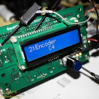
I have integrated a rotary encoder in the GenPIC utility board. With the combination of an LCD display and the rotary encoder you have all the ingredients for a functional user interface arranged neatly for a panel mount unit.
In the past I have simply set an interrupt to fire on the edge of one channel, then sampled the opposite channel to detect the direction. With the addition of a small delay to debounce the result. This worked well in previous devices, but this time I encountered trouble, the direction sampling was erratic, the value going up when it should have gone down and vice-versa.
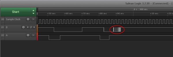
Breaking out my logic analyser I found out why, this particular encoder proved to be somewhat noisier than I had seen in the past, with notable periods of bouncing signals.
Hmmm… Need a better method of sampling and decoding the encoder output. I did not want to hack the hardware by adding an RC filter, this would entail cutting up my PCB’s. It should be accomplished in software.
I found a few methods of robustly decoding a rotary encoder on the web. One method I found that looked particularly good was found on the design of a cooking timer. In this design Eran Duchan uses a shift register, an edge detect, and a state machine. I expect the method works quite well, but when I started to execute it I realized just how much code it would take to implement the state machine, there should be a more elegant way.
Instead I took the best ideas from a few sources including Eran’s sampled shift register. My method looks for a single edge, the downstroke on the A channel, then checks the B channel for level. As the routine operates on a sampled shift register it requires all of the samples to match the prescribed bit pattern to filter out false edges.
|
1 2 3 4 5 6 7 8 |
bsf STATUS,C ;sample encoder values at 1kHz btfss userRead,userUIO0,A bcf STATUS,C rlcf userEncB,F,A bsf STATUS,C btfss userRead,userUIO1,A bcf STATUS,C rlcf userEncA,F,A |
First there are a few lines added to the interrupt routine. Executed on the same 1ms cycle used to generate the remainder of the clocks, the code samples both A and B channels from the encoder and shifts the samples into a pair of bytes. These bytes are further processed by a handler routine regularly called by the main loop.
|
1 2 3 4 5 6 7 8 9 10 11 12 13 14 15 16 17 18 19 20 21 22 23 24 25 |
;--------------------------------------------------------- ; UserEncCheck ; - check and debounce the rotary encoder ; - encoder A and B are at userPort bits 1 and 0 ; - sampled at 1KHz to the userEncA and userEncB registers ; - Bit pattern in the sample registers to detect rotation ; A: 111xx000 and B: xxx11xxx -> CW rotation ; A: 111xx000 and B: xxx00xxx -> CCW rotation ; - results indicated by setting flags in userFlag bits ; userEncUp and userEncDn ; UserEncCheck movf userEncA,W,A ;check A sample register andlw 0xE7 ;mask bits sublw 0xE0 ;check pattern btfss STATUS,Z return clrf userEncA,A ;ensure no double count movf userEncB,W,A ;check B level at edge andlw 0x18 ;mask center bits btfsc STATUS,Z ;check for CCW bsf userFlag,userEncDn,A sublw 0x18 ;check for CW btfsc STATUS,Z bsf userFlag,userEncUp,A return |
We first look at the A channel sampled bits. With the sampled bits shifted in from the left the code looks for the pattern 000xx111 to detect the downstroke. The two xx (do not care) bits indicate a two sample window to allow bouncing of the contact. With a 1ms sample period this is about 3ms long. If a match is found the shift register is cleared to insure the pattern is not found twice and double counted.
The code then looks for the level in the opposite channel using a reversed mask from the first check, looking for the level during the transition. If the B channel matches xxx00xxx then a counterclockwise (down) rotation is detected. Similarly if xxx11xxx is seen a clockwise (up) rotation is flagged. The results of either are indicated in a flag register for processing by another routine.
As you can see the solution is a compact bit of code, only 22 instructions when you include both the interrupt sampling code and the handler. The performance of this bit of code has proven to be quite reliable. Spin the encoder slowly or as fast as you can, the result is neatly one count per click of the encoder dial. I am quite happy with the results.

That went over most of our heads
aloha
What I do for fun 🙂
Nice! I never had to deal with the real details of rotary encoders. A long time ago, I used a 68332 that had time processing units with canned rotary encoder code. I used this to read an Altitude input on a control panel that controlled a Rockwell Collins display. But you had some fun!
Optical encoders, like those used in motors or inclinometers, usually have very clean outputs. The inexpensive mechanical units like this? Not so much. You need to take more care in decoding the signal.