
Over the years I have hand wired so many microcontroller PCB’s. Along with my own projects for myself there are more than a dozen of my little microcontroller devices at work about the observatory. The OSIRIS IR calibration source, the Keck 2 dome inclinometers, a precipitation sensor interface, the Keck 1 AO electronic vault temperature sensors, the weather mast fan and shelter controller, the list goes on. Anyplace a bit of electronic intelligence is needed for the task.
While a couple of my microcontroller designs have been laid out on proper circuit cards, like the SciMeasure camera exposure controllers, I have never laid out a general purpose microcontroller PCB. This is not for lack of thinking about it, so many times I have considered this could be so much easier if I could only invest a little time in a layout.
There are plenty of ready made PIC microcontroller development PCB’s available on the market, you can buy a handful from any of dozens of vendors. I have never found one that met my requirements. There are also plenty of other microcontroller options, the AVR’s and the Arduino systems, the STM32’s, and a powerful range of MSP offerings by TI.
Features? An LCD display and buttons, maybe a rotary encoder for adjusting some parameter. Two or more serial ports, an unusual feature. Support for WiFi and direct ethernet communications would be good, also an unusual feature on a small microcontroller development board. No need for USB! A common feature in many dev boards is USB support, while convenient in development, use of USB weds a device to a nearby computer. If I have a nearby computer why do I need a microcontroller for the task?
I really have no choice… Lay out my own development board. Actually I am going to call this a utility board as it is something to build real equipment around, not to play with.
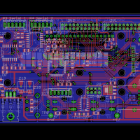
The design is presented here in its entirety, available for anyone to use as open hardware.
Design Realization
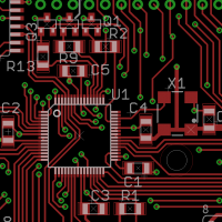
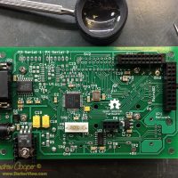
The GenPIC board is fairly small, a little under 3×5″, actually 2.9″ x 4.75″. This fits into a standard extruded aluminum case, the commonly available Hammond 1455J1201 which measures 5″ x 3″ x 1″. Component positions and traces allow use of the mounting rails. The power and serial connectors are laid out to allow access through the end panels of this case.
I choose a capable 8-bit microcontroller to build GenPIC around, the PIC18F66K80. With 64Kb of program space, 3.6Kb of RAM, two serial ports, 12-bit A/D on-board, and operating at up to 16MIPS, the processor is quite capable. While the capability of this microcontroller is sheer overkill for many of the tasks it will be used for, this processor is only $4 in small quantities from the usual vendors. This is not really any more expensive than lesser microcontrollers… Use it.
Open Source Hardware
![]()
Below you will find all source files needed to create this design. Provided are the original source files in common formats that should be easily loaded and modified by anyone familiar with the technology.
Documentation
Here you go, all of the design files needed for GenPIC. Some of these are in PDF for easy viewing, but the source files are also provided. The PCB is in Eagle format, I have the full version available, but this is a small PCB, it should load up in the free version.
| Second code release 14Jun2017 |
GenPIC Code r0.2 |
| First code release 11Feb2017 |
GenPIC Code r0.1 |
| Updated Manual 8Feb2017 |
GenPIC Manual rev A |
| First hardware release 20Dec2016 |
GenPIC Manual GenPIC Eagle PCB Design Files PCB Gerber CAM Files |
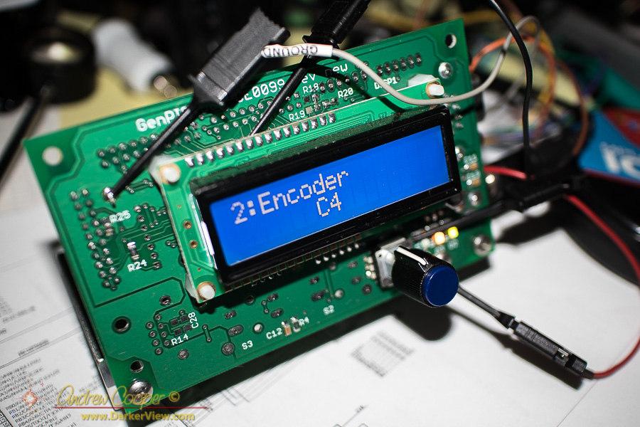
The first code revision is a test and demonstration release. It contains support for one serial port, an LCD character display, user input including the encoder and pushbuttons, the indicator LED’s, timer generation, analog input including onboard temperature readout.
Also included is a serial command interpreter implementing a serial interface usable with any serial terminal. There is also a user interface system with a state setup that provides multiple input screens. This should handle a wide array of basic control capabilities, either using the serial port or through using the LCD screen and the encoder. The code allows you to exercise many of the basic functions of the hardware and provide a framework on which a real application can be built.
Not all of the possible peripherals are supported in the current code release, these will come with time and need. Notably the ESP-01 and XPort are not yet supported. Look for further code releases as I have time.
Design Notes
There are quite a few options to consider when using the PCB. I have included many features that I think I might need, but some of those features must be traded off against others. The manual linked above contains a fair number of notes into configuring the PCB to the application, please download and refer to these notes before loading the PCB.
Errata
So far there are only a couple errors found in the first revision hardware…
- The footprint for the pushbuttons (S2 and S3) is problematic, the holes are the wrong size for the leads being a bit too small. The footprint for the rotary encoder is fine, will use that for the first builds.
- It was intended that a small heatsink could be used for the 7805 voltage regulator (U5), but one trace is in the way and the heatsink needs to be cut down a bit to avoid a possible short circuit from ground to +5V.
- The OE pin of the 3.3V level shift IC (U3 pin 8) is tied to ground. Unlike every other OE in the world it needs to be tied to VccA (3.3V on GenPIC). You can cut the short trace between OE and the nearby ground (a pin on S3) , then solder a pullup resistor between pins 8 and 1.

I came across your website from your post about the old troublemaker red LED on the telescope and I think your website is amazing! Great job!