
With an upcoming open house, everyone around the observatory is frantically trying to get everything in place. There will be all manner of science exhibits throughout the observatory headquarters complex. Exhibits about our research, controlling the telescopes, an IR camera display (Get your portrait in IR!), liquid nitrogen ice-cream, just a lot of fun.
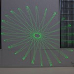
When attempting to teach something, a little eye-candy is helpful to catch the attention of the audience, particularly kids. Our group includes a laser engineer and a laser tech, so the use of lasers was obvious. There is little that catches the eyes of a kid faster than a bright laser beam. One of the first ideas they tossed on the table was a laser spirograph. After a few moments thought the answer was clear… I can build that!
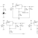
The circuit is very simple… There are three LM317 voltage regulators side by side. One regulator is set to three volts for the laser module, the remaining two are configured as variable regulators for the motors.
Experimentation was needed to find the operational range of the motors. The old tape recorder motors from my scrap box ran very nicely on anywhere from 4 to 16V, giving a nice range of speeds in the process. The motors are also double housed, running quietly. Well… at least they were quiet after the addition of a little light machine oil in the bronze bushings, these motors had been sitting in the scrap pile for at least two decades. When I first applied power I thought I might have to toss them they ran so rough!
The variable resistors for motor speed control are located in a remote box. This allows the projector itself to be placed just out of reach, but allows access to the controls for curious young minds to play with.
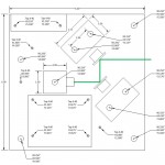
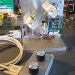
The frame was the result of an evening in the machine shop. I wanted a first class build here, something that can serve as an exhibit for more than this one event. Rummaging about the shop yielded some 1″ thick acrylic and scraps of aluminum that make for a very nice base. The laser module case is not electrically isolated, thus a plastic mount is a good idea, may as well make the motor mounts out of the same material.
The unit can be positioned to project the beam vertically or horizontally. I expect vertical to be the usual orientation, the pattern is projected on the ceiling for all to see. This keeps the beam away from any eyes, even though the beam is under 5mW and reasonably eye-safe.
Some of the other setups I have seen add a third motor and mirror, allowing for more complex patterns. I deliberately limited this to two mirrors, keeping the setup simple and more understandable, suitable for an educational exhibit. Likewise it was constructed to keep everything, including the circuitry as visible as possible.
The result is a clean, pretty build that looks good and works just as well.

This brings back memories. When I was still in grade school, probably sometime in the early ’60’s, I found an article in my Dad’s Popular Mechanics magazine to build a Spirograph. That was *long* before lasers, so we’ll just call it, the analog version. It used colored pens and papers, and worked great!
Tell you how to improve this. You need a way to accurately set the motor speeds, and control their motion exactly, as if they were geared together, so you have control of the pattern. For the DC motors, you substitute small high speed capable stepper motors, and write some software to synthesize the sine/cosine drive for the motors (you microstep them to get smooth motion). Now you will be able to reproduce patterns exactly. If you rearrange the geometry so the beams are striking the mirrors more perpendicularly, there will be less elliptical distortion. Another thing you can use instead of mirrors is the gratings from the cheap eyeglasses used at outdoor laser shows. You mount up a pair on motors and shoot the laser through where they overlap, parallel to the motor’s axes. Your display (with the gratings) will be awesome if you illuminate it with a multiline laser or an RGB laser set.
You say you are putting on a public display? Here’s an attention getter, easy and cheap to make! Set up a 5mW DPSS green laser (not direct diode laser, beam purity not good enough) and shoot it into a 1/2 inch thick block of wax (candle can be used if it’s undyed). Mount this stably on a table. When you look at it, the wax will glow with a green light that looks grainy. When you move sideways while looking at it, the grains will appear to shift, sideways, depending on the refraction of your eyes. If you are nearsighted, grains will move opposite, it you are farsighted, grains move the same way. Visit SuperOpticalSystems.com and buy a bunch of different spherical eyeglass lens blanks in different powers ($0.75 each). You try lenses until the grain movement stops, and you have your prescription! No matter how bad your vision, the grainy pattern will always be perfectly sharp!
The green laser from a pointer can be used, if you remove it and heat sink it to a metal block.