
Engineering is full of these little exercises. A set of numbers that must be arranged to achieve the desired result. In this case I need to keep time in a microcontroller, as there are events that I wish to occur every few seconds.
If you are using a crystal oscillator with the microcontroller, the frequency is reasonably accurate, about 50ppm at 25°C. As long as your application does not require high precision time, the result is a decent clock. Some form of clock or timekeeping is a very typical function in many microcontroller projects.
To do this I have a standard set of subroutines that I simply import into each microcontroller project. Well tested and used for years, requiring little effort to set up each time. The routines count seconds, minutes, hours, and even days and months if needed. This time is different… I am using a PIC18F25K80 in place of the PIC16’s I have used for decades. A newer processor, little differences in the hardware and instruction set… I need to rewrite the code.
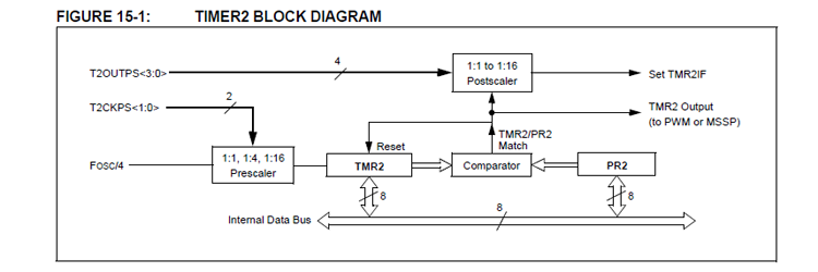
Timer 2 on the PIC18F25K80 is typical of timers found in both the PIC16 and PIC18 family. There are always a handful of timers in any microcontroller, usually with different arrangements for different tasks. At least one will be set up much like this one, with a comparator to provide a repeating fixed and timed interval.
The master processor clock (Fosc/4) is fed to a prescaler where the frequency can be divided by 1, 4 or 16. The result is used to increment a register (TMR2). This register is then compared against a set number (placed in PR2), when the count is reached the counter resets and starts over. The number of times this happens is fed to the postscaler, where a specific number of resets will set an interrupt flag. This postscaler can be set to any number from 1 to 16. Thus the interrupt flag (TMR2IF) will be set at a set frequency without any further intervention. You only need an interrupt routine to service this flag and update the clock registers.
As you can see there are a set of possible combinations, with the clock frequency, the prescaler, the comparator value, and the postscaler used to set the final frequency.
It turns out there is only one combination that really works for me this time. When setting up the scalers and comparator, it is necessary to avoid any combination that creates a frequency that is not a whole number of hertz. All of your inputs are integers, any number with a value on the right of a decimal point represents a time error you can not correct. No fractional numbers please.
An additional restriction is to keep every number in the system between 0 and 255, a value that can be stored in an eight bit register. Likewise the comparator can not be set for anything larger than 255.
I am using a 4MHz oscillator, thus Fosc is 1MHz. Use a divide by 16 prescaler and we now have 62500Hz fed to the counter. Set the counter for 125 and the output will be at 500Hz. Set the postscaler for 5 and you now have 100Hz, a convenient number that can be further handled in software and is slow enough to be handled by an interrupt routine.
Every time the timer interrupt flag is set I will update another counter, this will count from 99 down to 0 as it is easy to check for zero in assembly language. Every time this counter runs out the seconds counter will be incremented. Minutes, hours and anything else is handled the same way. It is very easy until you get to dates, which as any grade school student can tell you, are really messy.
These little puzzles are what makes engineering constantly challenging… And fun!
