The usual drill… A problem that can be solved by a bit of circuitry. In this case the gals in the lab were having trouble controlling the mix of gas to their cultures. They needed to feed much less CO2 to the mix, where the off-the-shelf flow gauges and needle valves became difficult to use much under one liter-per-minute.
A controller to modulate CO2 into a laboratory gas mix
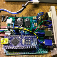
Simple solution… Build a gas modulator, something that could turn on the gas some percent of the time, allowing easy control of small amounts of CO2 to the mix. A timer and a gas solenoid… Easy.
There is nothing particularly interesting about the circuitry. A seven segment display, a few switches, and a power transistor to control an external solenoid. All very basic. It is the controller that is new, at least for me. An Arduino provides the programmable part of this project.
A minor code revision as I slowly get everything working properly. I am adding new modules as I need them for other projects.
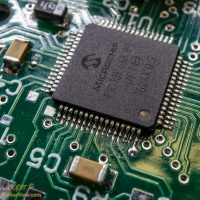
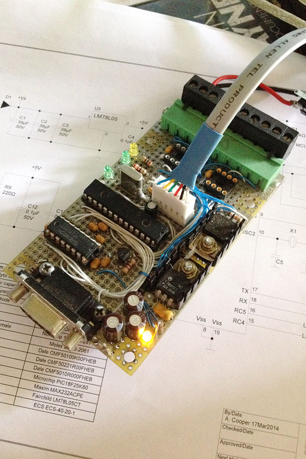
The microprocessor on a GenPIC PCB assemblyThe latest GenPIC deployed will be a coolant valve controller that allows remote control of some glycol valves in the AO bench. It is a pretty simple device, just four relays with some automatic timing rules and a serial control interface.
In the process I added support for the service connectors including parallel and simple serial modules to the GenPIC code base, may as well release it. Thus you get code release 0.2…
Next up will probably be SD card support, I have a project that needs to be finished requiring some reasonable data storage. Just ordered a few micro-SD card breakout boards from SparkFun
I took a break from working with a “big” microcontroller to work with a little one. The PIC12C671 is definitely little when compared with the PIC18F66K80 I am using in the GenPIC utility PCB. With less than 2k of program space and a mere 128 bytes of RAM it is definitely limited. Consider that the chip only has eight pins, two of which are power and ground, leaving six I/O pins to get the job done. No problem, I only need two I/O pins for this task and that few bytes of RAM is more than enough!
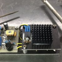
A simple heater using a bang-bang controller.This project is pretty basic… A bang-bang heater controller. This simple form of controller simply turns on and off as the temperature (or some other controlled parameter) goes up and down, there is no attempt to vary the output, all or nothing. Bang on, bang off, or simply a bang-bang controller as it is known in the trade.
A bang-bang controller is inherently reliable and stable because it uses two different control setpoints, a high and a low. Because these control points are separated by a large margin, called hysteresis, the controller will not oscillate or rapidly turn on and off. In this case the heater will not turn on until the temperature falls below 10°C and will not turn back off until the temperature rises above 15°C. That five degree margin is called hysteresis, and ensures a good period of time between on and off.
Over the years I have hand wired so many microcontroller PCB’s. Along with my own projects for myself there are more than a dozen of my little microcontroller devices at work about the observatory. The OSIRIS IR calibration source, the Keck 2 dome inclinometers, a precipitation sensor interface, the Keck 1 AO electronic vault temperature sensors, the weather mast fan and shelter controller, the list goes on. Anyplace a bit of electronic intelligence is needed for the task.
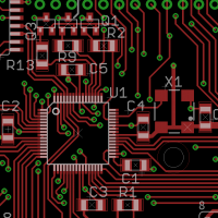
A PCB assembly in layoutOf course the challenge is that each of these controllers has been hand wired and built for a specific task. This takes a few hours of running little wires on a perfboard. And while I enjoy such wiring, it does make the task take notably longer.
While a couple of my microcontroller designs have been laid out on proper circuit cards, like the SciMeasure camera exposure controllers, I have never laid out a general purpose microcontroller PCB. This is not for lack of thinking about it, so many times I have considered this could be so much easier if I could only invest a little time in a layout.
Getting rain or snow on the primary mirrors is bad.
The Keck 2 primary mirrorThe normal method of detecting conditions that might lead to rain or snow is by monitoring the humidity or dew point. If the dew point approaches the current temperature, to within a few degrees the operators must close the domes. This is much the same thing as the humidity approaching 100%. Thus I have installed several new humidity/dew point/temperature sensors over the last few years. These replaced some old and troublesome equipment that had been in place for over a decade.
The problem… You can have both rain and snow occur with low humidity. Moist air above the telescope can produce rain or snow which falls into drier air at the summit level. This can catch the operators by surprise, a situation we have observed on a number of occasions.
To help detect this you can deploy a precipitation sensor, something some of the neighboring telescopes have done. The engineers over at CFHT were kind enough to show me the units they had installed during their remote operation project.
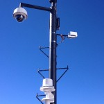
Various instruments atop the Keck Observatory weather mastYes, I just went out and bought one. Not just any old unit either… The best precipitation sensor I could locate on the market, a Vaisala DRD11A. The sensor uses a capacitive detection method. Moisture on the top of a plate will change the capacitance and trigger the sensor. The plate is tilted to allow rain to run off and heated to melt snowflakes and sleet. testing on my work bench showed this to be pretty effective and quite sensitive. Yes, you can visualize me sitting at the bench dripping water on a sensor… It worked.
Not that the project was finished there… The new sensor does not come with any sort of network interface. Rather surprising given that just about everything else Vaisala sells has either a serial interface or an ethernet interface. This sensor has just a couple simple outputs… A logic level indication of precipitation, an analog output representing roughly how much, and a frequency output representing the same thing. I needed to interface this unit to the network. As I have installed a terminal server in the rack below the weather mast, at the minimum I needed a serial port.
While I was at it there are a couple other little devices I want to install on the weather mast. These need a network interface as well. May as well put together another little PIC controller and assemble it all together in one neat little package. a few evenings of coding and I had my solution, an interface that allowed remote computer control and status read-back. How many microcontrollers do I have performing little tasks at the summit now? Quite a few.
“I suppose it is tempting, if the only tool you have is a hammer, to treat everything as if it were a nail.” – Abraham Maslow
The above statement is an adage that goes a long way to explaining many engineering decisions. Often referred to as Maslow’s Hammer it is a concept that has been well understood in science and technology for a very long time. In engineering we tend to use the tools we know to solve every problem in front of us, even if the tools we have may not be the best solutions.
A hand wired microcontroller circuit intended to be used to control a pair of inclinometers in the Keck 2 dome.There are good reasons to sometimes use the same old tools. The time and effort it takes to learn new tools, particularly with very complex technologies, is considerable. A decision needs to be made… The old tools may not be the most efficient way to solve the problem, but the time and effort it takes to change outweigh any gains to be made. Thus many wise engineers put off updating until the gains to be made are worth the investment of time and resources.
Or the old tools are simply obsolete and you are forced to update.
I am as guilty as any engineer in this. The major example, at least in my case, are microcontrollers. For many decades I have used Microchip PIC16F controllers each time I encountered a problem that required some form of complex control. Specifically I have always loved the PIC16F73 and the later PIC16F873 parts. they had everything I usually needed… A serial port, plenty of I/O pins, a few channels of 10-bit analog to digital, a convenient 28 pin DIP package. If I needed more I/O or more memory just step up to one of the larger packages like the PIC16F876.
Then Microsoft Windows 7 happened. How is this even related? The old versions of MPLAB I used to write the software and program the parts does not run of 64-bit Windows 7. When I updated my machine, I was forced to update to MPLAB X, a totally different platform. A new hammer to learn.
Engineering is full of these little exercises. A set of numbers that must be arranged to achieve the desired result. In this case I need to keep time in a microcontroller, as there are events that I wish to occur every few seconds.
If you are using a crystal oscillator with the microcontroller, the frequency is reasonably accurate, about 50ppm at 25°C. As long as your application does not require high precision time, the result is a decent clock. Some form of clock or timekeeping is a very typical function in many microcontroller projects.
To do this I have a standard set of subroutines that I simply import into each microcontroller project. Well tested and used for years, requiring little effort to set up each time. The routines count seconds, minutes, hours, and even days and months if needed. This time is different… I am using a PIC18F25K80 in place of the PIC16’s I have used for decades. A newer processor, little differences in the hardware and instruction set… I need to rewrite the code.
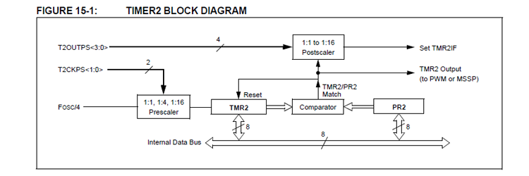
The layout of timer 2 in the PIC18F25K80 microcontroller
Timer 2 on the PIC18F25K80 is typical of timers found in both the PIC16 and PIC18 family. There are always a handful of timers in any microcontroller, usually with different arrangements for different tasks. At least one will be set up much like this one, with a comparator to provide a repeating fixed and timed interval.