
Another exhibit built for public outreach functions. It was completed and used for the recent W. M. Keck Observatory open house. You will also be able to see it at the upcoming AstroDay fun in Hilo.
Ray-tracing is a standard way to analyze optical designs. The technique allows the optical designer to follow the path of each ray of light through a system of lenses and mirrors. While ray tracing used to be done with pencil and paper, it is now done on a computer screen. What I had never seen was this process done in the physical. But I can figure out how…
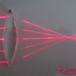
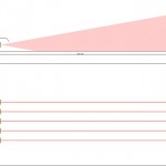
In the photo you can see the idea… Five red laser line modules are aligned across a table. Stick a lens section in the beams and you can observe refraction as it happens. Using a double convex lens, all of the beams converge to a focus. A clear demonstration of the basic principles of optics!
The laser modules are cheap Chinese units from Deal Extreme, a Hong Kong discount house. For $2.50 each, it is not a problem to buy a handful for a project like this. I did kill one unit during the construction. The case on the laser module is not electrically isolated and it came in contact with the aluminum frame while testing… Dead laser diode! To install the lasers I put heatshrink tubing around each module and used a nylon setscrew to lock them in place.
The lenses are from a set of educational optics available from Anchor Optics. This is a set of six acrylic lens and prism cross sections in a nice wooden case for about $35. The lenses are 3.5″ across, allowing for five beams with 0.75″ spacing.
The housing for the lasers is machined from a solid chunk of aluminum. Indeed this is the only part that really required much time to manufacture. It is not that much problem to machine, but it takes a few hours in the shop with aluminum chips flying. I really need to get a 3D printer for this sort of stuff.
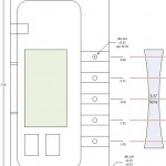
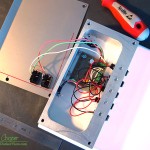
The small circuit board contains the voltage regulator for the lasers. An LM317 regulator does the job, nothing very exciting here. A terminal block distributes power, providing connections for all of the loose wires from each laser module. These screw terminals also make it easy to repair the unit. One switch controls the central beam, thus allowing demonstrations with one beam of light bending. The second switch controls the outer four beams.
In public the system worked very well indeed! A very physical representation of what is happening in a lens. There is nothing like a laser beam to catch a kid’s attention, and while I have that attention I can sneak in a little science!
