The Audine design is a solid CCD camera that can provide excellent operation. It does have a few interesting design issues that are discussed below...
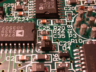
While first evaluating the performance of our cameras I noticed a problem with poor serial CTE in my first camera. This is usually a question of adjusting several of the bias and clock voltages to resolve. In the Audine only five of the voltages are adjustable, the vertical and horizontal clocks as well as the amplifier supply. The remainder of the bias voltages are set by means of selecting appropriate zener diodes. To adjust the voltage you need to change to diode. As long as the correct voltage is known beforehand there is no issue.
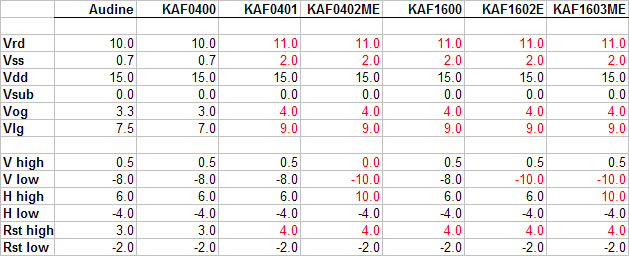
The questions start when comparing the voltages from the original Audine design to the Kodak data sheets. The Audine is clearly based around the older KAF0400 CCD, the voltages listed in the new KAF0402ME and KAF1603ME data sheets are different in several regards. Even the original KAF1600 requires slightly different settings for Vss, Vog, Reset and Vlg. Essentially anything other than an original KAF0400 will need different voltage settings. (See items in red in the table below)
Accommodating the newer chips is no problem with regard to the serial and horizontal voltages as the potentiometers allow adjustment to the new values. Zener diodes will need to be changed in order to set different bias voltages.
Kodak Data Sheets...
The serial CTE was certainly soft even though my original imaging has been done with an older KAF0401 CCD. Testing with a new KAF0402ME shows the same issue. I will be testing new voltages, starting with those listed in the CCD data sheets over the coming weeks. When this work is complete I will again evaluate the serial CTE of the cameras and hope to see an improvement.
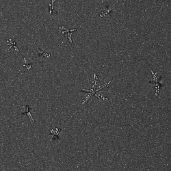
The weakest part of the Audine design and the issue that continues to baffle me is the poor chamber design in the basic Audine as published on the website. The chamber is not sealed and makes no provision for lowering the dew point around the CCD in order to prevent frost or condensation. This is odd considering the amount of custom machining needed to produce the case for the camera. Why not just design in a proper chamber when building the camera in the first place?
Many users of Audine cameras have gone to great lengths to deal with this issue. Reading through the many websites devoted to the Audine camera is very entertaining as you realize the magnitude of this issue as well as the creativity and skill that many amateurs bring to solving this issue. There are designs that fill the empty space in the camera with insulation material to reduce the air volume and available moisture. Designs that flood the camera with a heavy inert gas to displace the moisture. But the best answer to this issue seems to be complete redesigns of the mechanical arrangements to provide a sealed chamber.
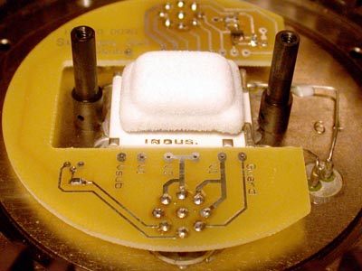
This is not an issue with our Audine+ cameras due to the excellent Photometrics chambers we are building our cameras around. The several chambers built as this time have been nitrogen purged. Condensation and frost should be no issue at very low temperatures.
The +/-15V supply that the Audine requires is an issue if field operation of the camera is required. Like most amateurs I am required to pack up my gear and drive out of the city into the Arizona desert to find the dark skies our hobby requires. This means I must operate from battery power, typically 12V sealed lead acid batteries. Converting 12V to +/-15V requires a DC/DC converter.
I can fully understand the lack of a +/-15V supply in the basic Audine. To create this voltage from 12V a switching power supply is required. Switching supplies can easily create electrical interference in other circuitry if not properly designed. The easiest method of keeping this noise out of the sensitive A/D system of the camera is to locate the source far from the camera, at the end of some sort of power supply cable.
It is possible to design a switching supply that can be built into the camera, but much more care is required. In my Audine plus I have done this, but even after designing dozens of switching supplies into other high performance cameras I will have to wait and see if this design will work properly. Each supply is a gamble, the design considerations are sometimes too subtle to see ahead of time and only a working prototype will reveal the flaws.
The last major issue left off the basic Audine is a mechanical shutter to stop incoming light from streaking the image during readout of the CCD. Fortunately the designers of the Audine provided the necessary interface and control functions for a shutter. It is then only necessary to decide on a method to build a shutter into your design.
Provided below is the shutter circuit I am using to drive the shutter in our Audine+. This circuit can be used directly or adapted to drive several commercially available shutters including the Uniblitz designs. It features a large capacitor bank that is charged to a higher voltage, about 10V, to provide the high current pulse needed to open the shutter in a few milliseconds and a lower holding current that just holds the shutter during the exposure without overheating the shutter coil. The recharge time on the capacitor bank is much shorter than the readout time of the Audine so the shutter is ready to go before the next exposure. Because the design incorporates a switching supply it must be properly isolated from the main camera electronics.
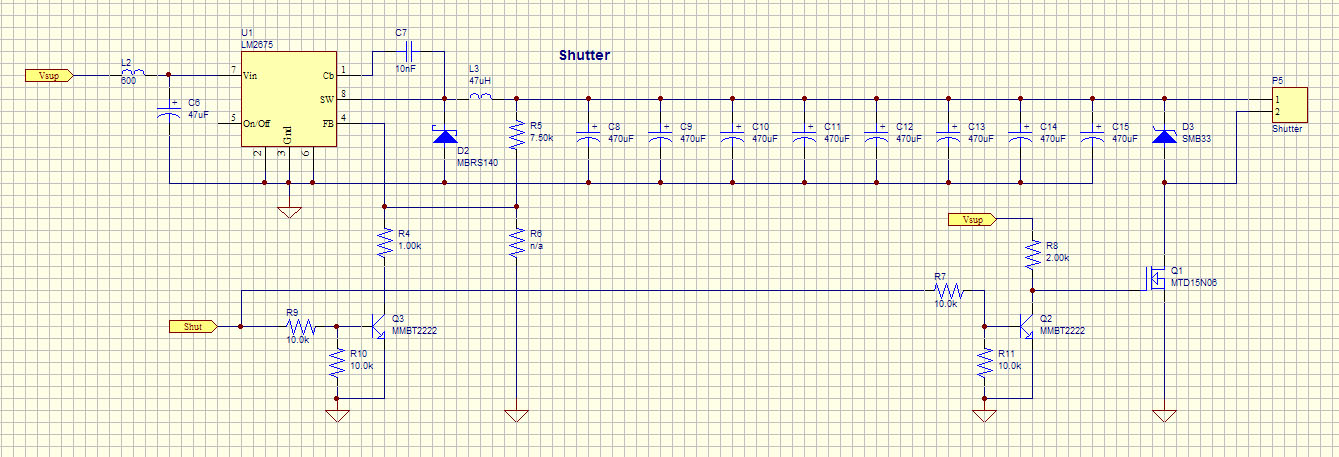
This design is setup to function from a single 12V supply as provided by a 12V battery, the drive signal 'Shut' can be connected directly to the shutter pin 11 of C2 on the original Audine schematics. In testing the design works very well. It is sometimes necessary to change the voltage divider resistors to accomodate other shutters depending on the neccesary open and hold voltages.