
I took a break from working with a “big” microcontroller to work with a little one. The PIC12C671 is definitely little when compared with the PIC18F66K80 I am using in the GenPIC utility PCB. With less than 2k of program space and a mere 128 bytes of RAM it is definitely limited. Consider that the chip only has eight pins, two of which are power and ground, leaving six I/O pins to get the job done. No problem, I only need two I/O pins for this task and that few bytes of RAM is more than enough!
A bang-bang controller is inherently reliable and stable because it uses two different control setpoints, a high and a low. Because these control points are separated by a large margin, called hysteresis, the controller will not oscillate or rapidly turn on and off. In this case the heater will not turn on until the temperature falls below 10°C and will not turn back off until the temperature rises above 15°C. That five degree margin is called hysteresis, and ensures a good period of time between on and off.
Shown in the chart here is the actual performance of this heater in a test. OK, this test is just the heater, placed in a small cardboard box, which in turn was placed in a refrigerator. All the better as this particular refrigerator was the break-room fridge at Keck Observatory HQ. Nothing like a mysterious box, trailing wires out of the break-room refrigerator, connected to a little computer looking thingy to properly secure my status as an electronic hacker and geek. No worries, that reputation is quite secure.
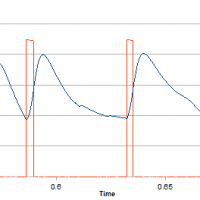
The chart also demonstrates the problems with a bang-bang controller. There is a large swing in the controlled parameter, often an unacceptable swing. Not a problem for this application, perhaps a problem for other uses. Consider using this control swing to heat a room, many would find the result, alternating between too warm or too cold, to be uncomfortable.
Yes, you could move the control points closer, but there will be some swing simply due to the delays inherent in a large system where things take time to happen. By the time the room heats up and the heater turns off it is already too late, the controlled parameter may overshoot the desired value by quite a bit. Setting the control points closer also creates a system that turns on and off more rapidly. Some equipment, such a gas-fired furnace, may not operate efficiently when cycled quickly.
Heating and cooling are often controlled by bang-bang controllers, simple thermostats. A furnace or air conditioner is an all-or-nothing device, you can turn it on or off, with nothing in between. If you look closely at the programming of the thermostat you will find two settings… The desired temperature, and if you look closer the allowed temperature swing or hysteresis.
If tighter control is required the usual answer is to move to some sort of proportional PID control in place of the bang-bang. Using a PID servo control scheme it is possible to tune the system to avoid large overshoots and achieve vastly better control of the system. The price is a far more sophisticated design and the need to find the correct control parameters, often a challenging task. There are entire textbooks on tuning PID servo loops!
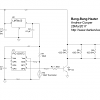
As you can see below, this circuit is extremely simple, the only real work is in the code. Programming this little PIC micro is just fun. There is not much you need to worry about. Only a few control registers, only six I/O pins of which I am using only two, the only peripherals I am using using are the A/D converter and the timer.
The PIC12C671 has been moved to the “not recommended for new designs” status by Microchip, superseded by the PIC12C675. Why use it? I still have a few sitting around in the parts pile, including a double handful of the UV-EPROM versions needed for development and testing. I did quite a few designs based on this little chip, mostly battery chargers, back during my employment for C&D Technologies. I have some memories wrapped up in this little chip.
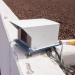
The heating is minimal, about eight watts, but it should be enough to warm the small box containing the camera at least a few degrees. This is about all I can draw from the power supply that also serves the camera and window heater.
I have included the entire design here, both the schematic and the code. Feel free to use any or all of it. You will need MPLAB and a device programmer to program the microcontroller. Otherwise the circuit is simple to build and should provide no difficulty.
|
1 2 3 4 5 6 7 8 9 10 11 12 13 14 15 16 17 18 19 20 |
;------------------------------------------------------------------------------ ; BangBang.asm ; - simple bang-bang heater control based on a thermistor ; ; Andrew Cooper ; http://www.darkerview.com ; CC BY-SA Creative Commons Share Alike ; ; 25Mar2017 A. Cooper ; - initial version ; ;------------------------------------------------------------------------------ list p=12c672 ;define processor #include <pic12c672.inc> ;processor specific stuff errorlevel -302 ;suppress message 302 __CONFIG _CP_OFF&_WDT_OFF&_MCLRE_OFF&_PWRTE_ON&_INTRC_OSC ;- RC Osc Calibration --------------------------------------------------------- org 0x7FF |
The code is simple non-relocatable assembler, not much need for dynamic code arrangement in such a small project. The resulting code consumes a whopping 138 bytes out of the two kilobytes available. Only 28 bytes of RAM are needed, half of that is the averaging table for the analog data. Pretty simple!
To further ensure stability of this controller the temperature is measured every second and averaged over the last 16 seconds as a boxcar average. Thus the temperature value used for control only changes once each second and should change slowly. Even if a wildly spurious value appears the boxcar average should devalue any stray readings.
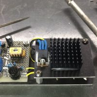
This sort of simple circuit may not present any huge engineering challenge, rather the fun lies in making the circuit elegant and robust, an expression of skill. Everything needed came from the parts pile, nothing needed to be ordered.
The hardware took a single evening to assemble, the aluminum bits manufactured in the observatory machine shop that afternoon. The software likewise was done in a single day, something to do while taking breaks from cleaning the carpets and laundry on a busy Sunday. Testing took a bit longer, but that was mostly just letting it run while a data logger kept watch.
