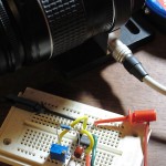


When you want to see the stars, find someplace dark

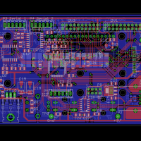
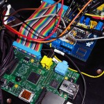
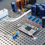
I am currently putting the finishing touches on another printed circuit board.
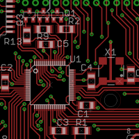
A PCB is laid out with specialized software, drawn on the computer screen. The software can then generate CAM files that are sent to a board house, a manufacturer who can take these files and create a physical PCB. The PCB is thin layers of copper etched to create the patterns of traces laminated onto a fiberglass substrate. When designing the PCB each component, each copper conductor, each trace, is carefully positioned by the designer on the screen, dragging objects colored lines about to create a solution.
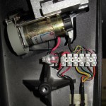
It is always a good day when I drive up the mountain to a broken telescope, then drive down leaving a working telescope. Easy to say, not always easy to accomplish, the simple statement obscuring a day of struggle to solve the problem and fix it.
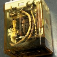
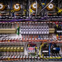
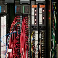
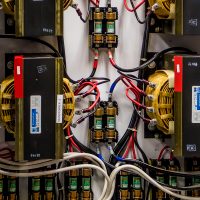
The Keck 2 telescope drive is a complex beast of dozens of relays, miles of cabling, servo amplifiers and power supplies, plus several circuit boards designed and built in the 1980’s holding a bewildering array of arcane logic.
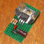
I am no stranger to point-to-point wiring. I routinely use the technique to build small circuit boards. Well done point-to-point is a permanent and reliable way to build a complex electronic device.
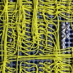
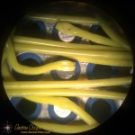
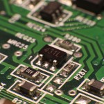
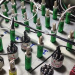
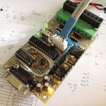
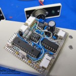
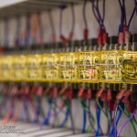
But then there is this circuit board assembly I came across… At first glance it looks like a wire wrap board. But there are no posts, the wires are flush to the board. Neither is it traditional point-to-point wiring, the wires are not terminated to solder pads beside the pins being connected. I had never seen a construction technique like this.
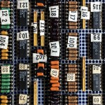
The board is an old PCB assembly found in a storage cabinet while clearing out the old junk that has accumulated about the observatory. No idea where it came from or what it was used for, the only clue is some writing on the box… “Keck level shifter”, Perhaps a piece of a detector controller? Someone clearly put a lot of work into the board at one time, now it sits in my office as unknown junk. It is the odd construction technique that caught my eye and led me to hang on to the board, at least temporarily. What is this?
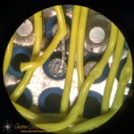
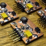
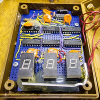
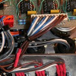
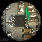
A closer look under a microscope shows a connection clearly made by some sort of spot welder. There is a neat little hole through the insulation at each connection. Stripping back the insulation reveals a very neatly welded wire. Each wire is welded to the flat bottom of each pin socket. Every component pin is socketed, this includes all passives, which are mounted to headers and plugged in alongside the IC’s.
There are a number of advantages to this wiring method… The connections should be very reliable and robust, the weld is a nearly ideal electrical connection. As no connection pads are needed beside each socket the density is much higher using less circuit board real estate per component, you can cram more on the board. Interestingly the connection technique can be used without terminating the wire, daisy chaining to the next connection point.
There are disadvantages as well… The method clearly requires some sort of welding equipment with perhaps an automatic wire feeder and cutter, a built-in microscope for positioning the weld, and more. Clearly an expensive piece of kit. No components can be present during welding as they may suffer damage from the high electrical currents needed for spot welding, thus everything must be socketed. All those little sockets are expensive! Rework or repair would need to be done with more traditional soldering techniques.
I would love to see the machine that did this board assembly. Maybe even a chance to use it. More information on the process seems difficult to find on the web without a trade name or other keyword that would clearly identify the process.
Not that these welded wires would be of much use today. The technique is clearly ideal for complex digital circuits of the style and speed that was common through the 1980’s to around 2000 or so. After that the prevalence of surface mount technology and the abandonment of the DIP package would doom the method. Modern high speed circuits benefit greatly from the more controlled traces of a printed circuit board and would not fare well on a welded wire board. In these days of easy computer layout and cheap printed circuit boards welding would not be my fabrication method of choice.