How do you power a device that must stay on through an event that may cause a power outage? Battery backup of course. But that answer leads to whole new level of complications. There must be a circuit in place to allow power to be drawn from the battery or the power supply. The proper battery technology should be chosen. You need a another circuit to care for the battery, allowing for very long term reliability. Long term? Years.
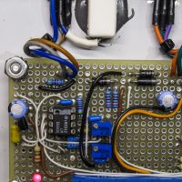
A 6V lead-acid battery charger based on the venerable LM555.A good answer for the battery technology is sealed lead-acid. A properly used lead-acid battery should last a decade or more while providing power to operate for over a day. Lead-acid may not be a good choice for a portable device where weight and size are the primary considerations. But for a stationary application this venerable technology is a good choice.
What about the charge circuit? A simple charger that can fully charge the battery, but not overcharge the battery is needed. In the case of lead-acid charging is usually accomplished by charging to a chosen voltage before shutting off or lower the voltage to a safe lower value called a “float charge”.
I have had hardware for a while now, it is about time I release some firmware that actually runs it.
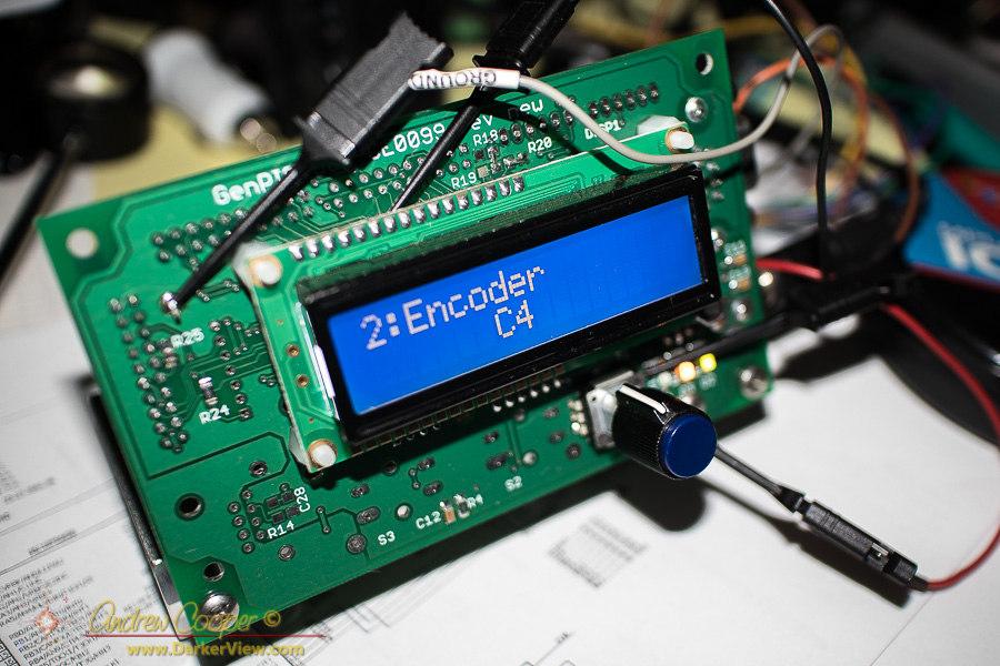
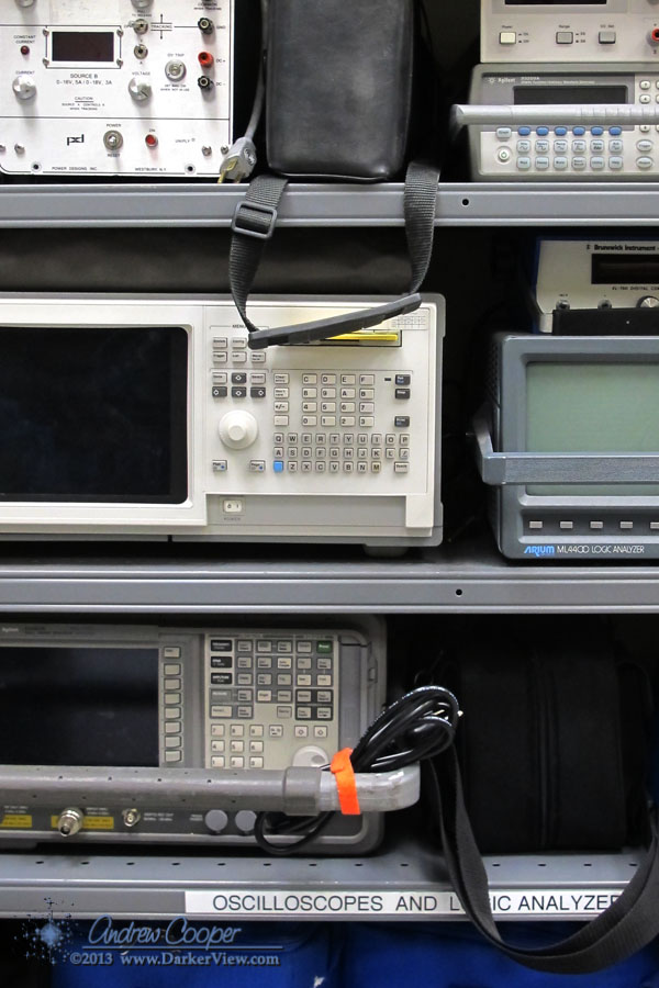
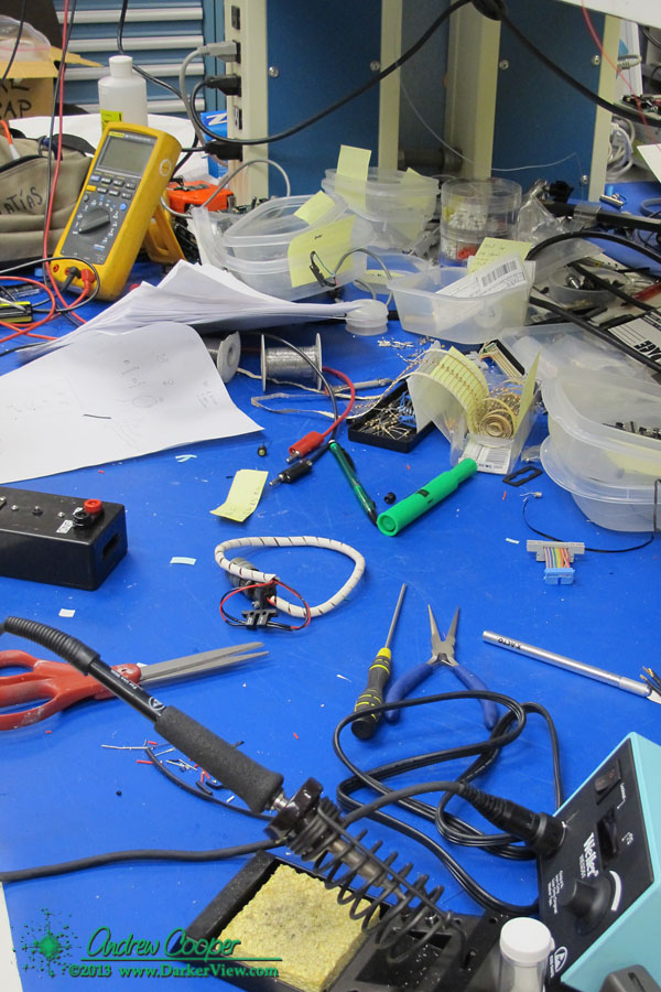
The development setup in use generating the first software release for the GenPIC utility PCBHere it is!
The first GenPIC code revision is a test and demonstration release. It contains support for one serial port, an LCD character display, user input including the encoder and pushbuttons, the indicator LED’s, timer generation, analog input including onboard temperature readout.
Also included is a serial command interpreter implementing a serial interface usable with any serial terminal. There is also a user interface system with a state setup that provides multiple input screens. This should handle a wide array of basic control capabilities, either using the serial port or through using the LCD screen and the encoder.
The code allows you to exercise many of the basic functions of the hardware and provide a framework on which a real application can be built.
It works, it runs, it looks fairly good. Now time to make something useful with it…
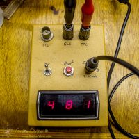
I have been messing about with electronic circuitry for almost four decades. I recently came across an early example of my work. The device is a digital event counter built around classic 74xx series logic. A chain of 74190 decade counters feed a set of 7447 decoder drivers and seven segment LED displays. A plastic project case with switches and connectors reminds me I have been building little devices for a very long time.
A digital event counter built when I was fifteen years old.In some ways the unit is very similar to one of my more recent builds. Perfboard and point-to-point wiring are still standard construction techniques. The technology may have changed across the years, becoming far more complex, but some parts have remained the same.
The Keck Adaptive Optics systems are workhorse scientific instruments. Equipment that has resulted in so many great astronomical discoveries. The AO systems have also seen a great deal of improvements and upgrades through the years. New computers, a new wave-front controller, guide star lasers added, new cameras, different science instruments, and much more.
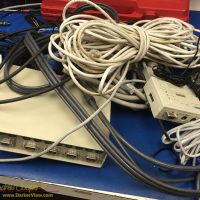
A pile of electronic cruft removed from the Keck 2 AO enclosure.While the new gear has improved the systems dramatically, the result is that there is a fair amount of disused bit and pieces hanging about. Mostly cabling, but more than a few unused boxes of electronic gear are still sitting in place in the racks.
Eventually I just get fed up with it and insist we spend some time getting rid of it. With no AO use scheduled for a while there is a chance to spend a couple days ripping out this pile of cruft. Identifying and removing unused boxes. Following cables to nowhere, wire cutters in hand to snip away the multitude of nylon zip-ties.
We remove three large armloads of cables and other gear, carring the pile down to the electronics lab for sorting through and disposal. Most of it is horribly obsolete, things like KVM’s for PS/2 style mice and keyboards, or cables for old Sun computers. Most of it will simply be thrown out. It feels so good to get it out of AO and to clean up the place a little.
I called this pile of junk cruft, a word that drew funny looks from my co-workers. You don’t know what cruft is? What sort of nerds are you? Sorry, cruft is what I have always called leftover technical junk.
Cruft is jargon for anything that is left over, redundant and getting in the way. It is used particularly for superseded and unused technical and electronic hardware and useless, superfluous or dysfunctional elements in computer software. – Wikipedia
It turns out that the word has a long history in engineering and computer science with a heritage that includes MIT and Harvard. It is indeed the proper word for the detritus that had been accumulating in the AO vault.
I am no stranger to point-to-pointwiring. I routinely use the technique to build small circuit boards. Well done point-to-point is a permanent and reliable way to build a complex electronic device.
Welded point-to-point wiring on a complex circuit board
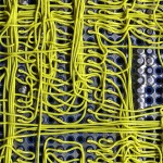
But then there is this circuit board assembly I came across… At first glance it looks like a wire wrap board. But there are no posts, the wires are flush to the board. Neither is it traditional point-to-point wiring, the wires are not terminated to solder pads beside the pins being connected. I had never seen a construction technique like this.
The board is an old PCB assembly found in a storage cabinet while clearing out the old junk that has accumulated about the observatory. No idea where it came from or what it was used for, the only clue is some writing on the box… “Keck level shifter”, Perhaps a piece of a detector controller? Someone clearly put a lot of work into the board at one time, now it sits in my office as unknown junk. It is the odd construction technique that caught my eye and led me to hang on to the board, at least temporarily. What is this?
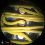
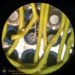
A closer look under a microscope shows a connection clearly made by some sort of spot welder. There is a neat little hole through the insulation at each connection. Stripping back the insulation reveals a very neatly welded wire. Each wire is welded to the flat bottom of each pin socket. Every component pin is socketed, this includes all passives, which are mounted to headers and plugged in alongside the IC’s.
There are a number of advantages to this wiring method… The connections should be very reliable and robust, the weld is a nearly ideal electrical connection. As no connection pads are needed beside each socket the density is much higher using less circuit board real estate per component, you can cram more on the board. Interestingly the connection technique can be used without terminating the wire, daisy chaining to the next connection point.
There are disadvantages as well… The method clearly requires some sort of welding equipment with perhaps an automatic wire feeder and cutter, a built-in microscope for positioning the weld, and more. Clearly an expensive piece of kit. No components can be present during welding as they may suffer damage from the high electrical currents needed for spot welding, thus everything must be socketed. All those little sockets are expensive! Rework or repair would need to be done with more traditional soldering techniques.
I would love to see the machine that did this board assembly. Maybe even a chance to use it. More information on the process seems difficult to find on the web without a trade name or other keyword that would clearly identify the process.
Not that these welded wires would be of much use today. The technique is clearly ideal for complex digital circuits of the style and speed that was common through the 1980’s to around 2000 or so. After that the prevalence of surface mount technology and the abandonment of the DIP package would doom the method. Modern high speed circuits benefit greatly from the more controlled traces of a printed circuit board and would not fare well on a welded wire board. In these days of easy computer layout and cheap printed circuit boards welding would not be my fabrication method of choice.
Welded point-to-point wiring on a complex circuit board
Detail of a connection in welded point-to-point wiring on a complex circuit board
Detail of a weld in welded point-to-point wiring on a complex circuit board
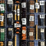
Component side of a welded point-to-point circuit asembly
The new dome and shutter control PLC finally had it’s first night on-sky. The result? No fuss, no trouble, it just worked as designed. To have everything go so smoothly was very satisfying. So much work and trouble, so much worry on my part. Yes, I had performed two days of testing, but this would be on-sky, at night, the final test.
The Keck 2 dome in the glow of sunsetI arrived on the summit after lunch to convert the system, removing the old PLC and connecting the new controller. A few tests, moving the dome and shutters showed that everything seemed to be working. The plan was to stay into the night to insure that if there was trouble I was on hand to fix it, or convert back to the older system.
As the last rays of sunset gleamed I took Capt. Marvel (the radio controller for the dome) and went up onto the roof. From there I commanded the shutters to open, watching with satisfaction as the giant assemblies smoothly opened to the night.
Better yet, the night was partially used for testing the new telescope control system, the TCSU project. Thus the new PLC was tested with both the old system and the new telescope control system.
The result of all my worry was a simple one line write-up from the telescope operator in the logs the next morning… “New dome PLC operations successful. No issues.”
Like most electronic hobbyists, I have an odd relationship with Radio Shack. In our youth it was the one local place you could buy basic components… Resistors, connectors, wire and other parts could be found there, without waiting a week for an order from a mail order catalog. The selection was always pretty sparse, the quality was hit or miss, and the prices were too high. But, if you needed something quickly it was the place.
The Radio Shack location in Waimea in the KTA centerI even worked in a store for a summer in high school, learning what it was like on the other side of the counter. An experience that left me wondering why anyone would want to work in retail sales.
Then for many years, through the 90’s and the early part of the 00’s Radio Shack neglected the hobbyist business, concentrating on cell phones and accessories. Recently they have returned to their roots, restoring the kits and components section of the store. This time with Arduinos and other more modern technology. It was a move that many in the electronics community greeted with some enthusiasm.
Still, in recent visits looking for a last minute component I have found the selection just too minimal to be truly useful.
Word that Radio Shack is filing for bankruptcy and closing 1,750 stores is no surprise. According to news report the corporation claims $1.2 billion in assets and $1.4 billion in liabilities.
Apparently our local store in Waimea is not slated for closure in this first round. The future of any particular store is far from certain. Sprint has agreed to purchase many of the closed stores, but details are far from complete. Certainly many of the stores occupy desirable locations and are ripe for acquisition.
What emerges from bankruptcy will be interesting to see. But my guess is that the Radio Shack that has long been a fixture in our lives is gone.
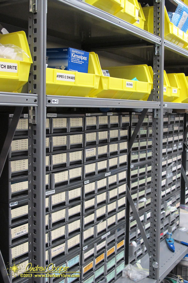
The summit of Mauna Kea is a long way from anywhere on this island. If something breaks we really need to have the parts on-hand to fix it. The result is that just about any unclaimed space in the building is used to store spare parts. We have stuff stashed everywhere!
This goes for the electronics lab too. A little bit of everything we might need is available. Now you just need to spend a few months learning where to find everything…
Racks and bins of supplies in the Keck electronics lab.