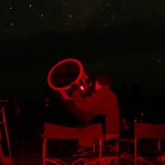
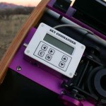
When your Celestron GPS telescope will not get GPS fix for a long time, or the GPS will not work at all, it is time to replace the battery on the GPS receiver board. Another symtom is when the telescope may get a fix, but it is incorrect, the time or location no where close.
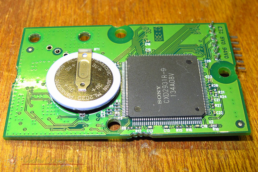
The Celestron GPS telescope GPS module with the original batteryInstructions for replacing the battery are posted elsewhere about the web. There are excellent instructions for battery replacement on the NexStar Resource Site. It was those instructions I was following when I was recently replacing the battery in our ‘scope.
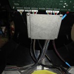
The GPS board is found in the main section on the oldest telescopes, but located in the arm in later ‘scopes. Our is located in the arm, a small circuit card just under the inside plastic panel connected to an antenna by a cable. Simply remove the four screws holding the plastic panel and you have access. The antenna cable can be disconnected with some gentle tugging, two screws for the board, one more connector and the board comes out. The battery is found hidden on the underside of the PCB.
With Jupiter still near opposition and Mars opposition approaching I would like to do a little high resolution planetary imaging. For planetary I use our Nexstar 11″ telescope, with 2800mm of focal length is has the high magnification needed.
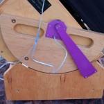
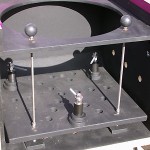
Aligning our Nexstar 11″ with a Hotech CT Collimation ToolOne lesson in high resolution imaging is that collimation matters. Having the optics in your telescope precisely aligned makes all the difference in the results. A small misalignment will result in mushy images that will not quite focus properly. No amount of fancy image processing will salvage the image.
The Nexstar has not been giving me the results I know it is capable of. I shot Venus just before inferior conjunction and noted that there was probably some issues in collimation that were not addressed in the quick star collimation I had performed.
Thus I borrowed a Hotech CT Laser Collimatior from a friend. The collimator is an interesting piece of kit, enabling the user to check more than simple the tip-tilt of the secondary.
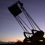
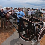
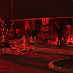
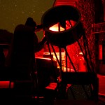
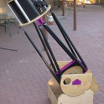
Today an amateur astronomy icon passed away. John Dobson popularized the very simple design of telescope that came to bear his name, the Dobsonian. As a Vedantan monk John possessed few material means, pursuing a passion for telescope building in the monastery garden shed he designed a telescope that could be built from whatever scrap parts he could scavenge. He could often be found around San Fransisco showing the wonders of the night sky to anyone who would look through one of his telescopes. His infectious enthusiasm for astronomy led him to help co-found the San Francisco Sidewalk Astronomers.
Chris Fuld using his monster 40″ dobsonian at Oregon Star Party 2013
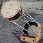
The Dobsonian is a telescope that is characterized by an extraordinary simple and robust design. Made of plywood and other hardware store parts, there was nothing in the design that could not be built by hand.
The optical layout is a standard Newtonian design with the eyepiece at the front of the telescope. This allows the heavy primary mirror to be located quite close to the ground. The entire telescope rotates on a simple lazy-suzan azimuth bearing made of plywood, formica and teflon blocks. A simple set of trunnions allows the telescope to be raised and lowered in elevation.
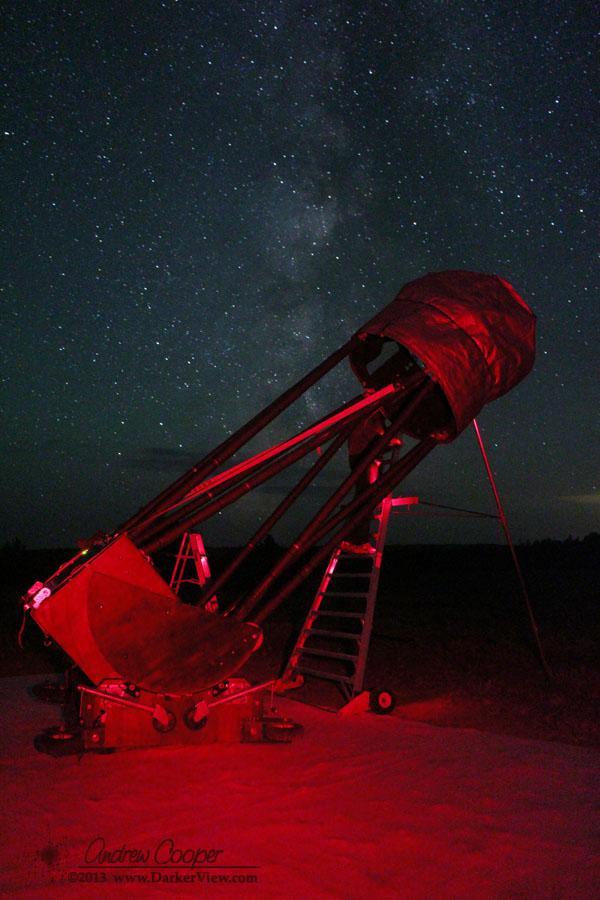
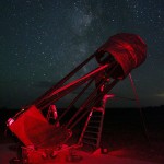
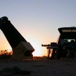
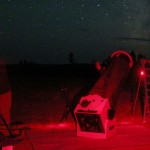
Steve Dillinger’s 20″ Dob awaiting full dark at Sentinel, AZ with Venus and the Moon shining behind
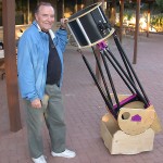
The Dob brought large aperture astronomy into reach of thousands of backyard observers. Anyone with a modicum of skill could build a Dob in a garage with simple hand tools. Commercial designs soon appeared at very affordable prices.
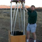
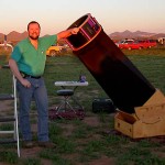
Amateur telescope makers have built upon John’s ideas, creating elegant designs that far surpass those simple telescopes made from scrap. Aircraft grade plywood, machined aluminum frames, carbon fiber and computerized controls are common in modern Dobsonians. The design can be scaled up, Dobsonians are sometimes enormous, with telescopes of 30 or 40 inches aperture seen at many star parties. At OSP last year I setup next to a 40″ built by Chris Fuld, a monster telescope built by hand.
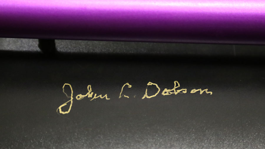
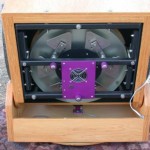
John spent much of his later life touring wherever dark skies, telescopes and people could be found. This often included national parks and regional star parties. I met John a few times across the years, at Grand Canyon Star Party and at an evening observing session at Starizona, an astronomy shop in Tucson. His signature graces the secondary cage of my 18″ f/4.5 Dobsonian, Deep Violet, beside the signature of David Levy.
John Dobson’s signature on the secondary cage of Deep Violet
John was also a proponent of a decidedly non-standard cosmology, believing that the Big-Bang model had fatal flaws. His alternate ideas make… Uh? Interesting reading. He describes a recycling steady state cosmos heavily influenced by the teachings of eastern religions and mystical thought.
John Dobson died today, 15 January 2014 at the age of 98 in Burbank, California. John leaves behind a son, many friends, and a community indebted by his contributions to amateur astronomy. My friend Dean Ketelsen knew John far better than I did, I suggest you read his notes on his passing.
I spent a few moments and put all of the photos of dobsonian telescopes that have appeared here on Darker View into a gallery. The photos are just a little sliver of what John Dobson meant to amateur astronomy…
Steve Dillinger’s 20″ Dob awaiting full dark at Sentinel, AZ with Venus and the Moon shining behind
Detail of an elevation bearing and encoder
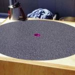
The 18 point mirror cell, built to the plans from Barry & Kriege
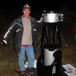
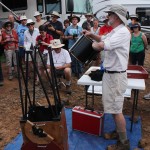
Ken Jones observes with his 18″ dobsonian
First light atop Kitt Peak
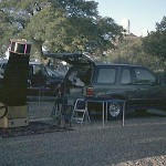
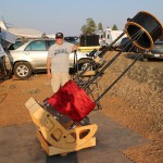
Preparing to set up the telescope
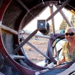
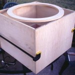
Looking into the mirror box without the primary and mount in place
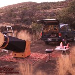
Under Arizona stars at Las Cienegas
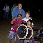
Tony shows a group of enthusiastic student views with his 12.5″ dob.
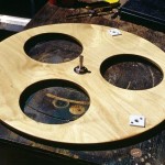
The ground board with center pivot and teflon pads in place
Olivier beside his new telescope, a 12″ Orion Dobsonian
Deep Violet at the Mauna Kea Visitor Information Station
Mark Folkerts preparing his equipment for the night
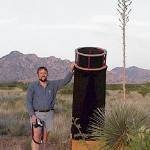
Deep Violet set up neat the Dragoon Mountains in Southern Arizona
Chris Fuld collimating his 40.5 inch dobsonian
David Nemo and his handmade 20″ string telescope
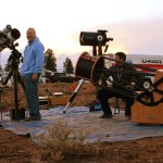
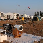
The author’s setup awaiting a dark December sky with Deep Violet
Gluing the laminate to the rocker box to create the azimuth bearing
Chris Fuld using his monster 40″ dobsonian at Oregon Star Party 2013
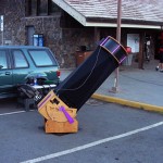
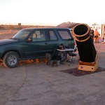
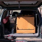
Deep Violet packed in the rear of my Ford Explorer
The rocker box between coats of polyurethane
The 18″ setup at 9000ft on the side of Mauna Kea
Sunset at Arizona City awaiting dark
Chris Tribe with his 20″ f/4.5 built from ultralight materialsChris Tribe with his 20 inch f/4.5 built from ultralight materials
Ken and Ann Jones oberving with their 18″ at Oregon Star Party 2013
Looking at the mounted mirror cell and primary mirror
Looking down the observing line at Oregon Star Party 2013
Routing the top of the rocker box to create the elevation bearing
Looking into the mirror box with the mirror mount in place
Gluing the mirror box with a cage ring atop to check the fit
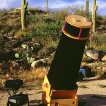
Setup among the saguaros of the Tortillita Mountians
The Sky Commander digital setting circles mounted to the secondary cage
Almost all of the big dobsonian telescopes to be found on Hawai’i show up at the VIS for the night.
Bob Clements demonstrates his 10″ dobsonian with an equatorial platform
Assembling the truss tubes and secondary cage
Cliff at the eyepiece of his 24″
Deep Violet fully assembled and nearly ready for dark
The author waiting for dark at the 2005 All Arizona Messier Marathon with my usual visual setup including Deep Violet
Gluing the gussets into the mirror box
Secondary Cage with the focuser, digital setting circles and Telrad
I have only had three telescopes given to me this year. Telescopes in various states of disrepair. I usually fix them up, clean them up, and find a new home for them.
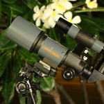
It was Julia who gave me this little bit of fun… A Celestron 62mm f/4.8 Cometron. A small refractor intended for low power viewing. Prefect for viewing comets or other wide field objects.
A Celestron Cometron 62mm f/4.8 telescope.These little refracting telescopes were sold in the 1980’s to capitalize on the comet Halley mania. Sold bearing the Celestron name, they were actually built by Vixen. They continued in production for many years as they proved relatively popular. The Cometron name has been used for a number of small telescopes over the years, but, as far as I know, this is the original.
The ‘scope I was given was in pretty good shape. Nothing broken or badly damaged. The optics dirty but free of coating damage or uncleanable grime. All that was require was disassembly and a good cleaning to remove dirt, spider webs, and a few cockroach egg cases.
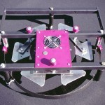
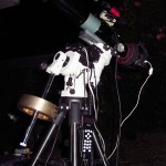
A small, light telescope mount, a small refractor, and a modern autoguider. Seems like a perfect setup! There are a few issues…
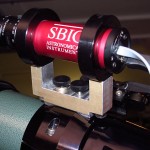
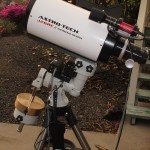
The setup is pretty straightforward. A TeleVue 76mm riding atop the iOptron ZEQ25 mount. Atop the TV-76 is a red dot finder and an SBIG STi autoguider. The guider is attached with a bit of custom machining and uses the SBIG accessory kit, including a 100mm lens giving a 2.7 x 2.0 degree field of view. With such a wide field of view the guider also functions as a finder to aid in aligning and framing the photographic telescope.
The iOptron ZEQ25 set up for astrophotography with a TeleVue-76 and Canon 60DThe arrangement is controlled by a laptop, either an older 17″ laptop, finding a second life in the astrophoto rig. Or for a more portable, and less power hungry setup, a small netbook can be used. It may be desirable to set up the iPad for telescope control, removing this function from the laptop. If it were not for guiding the computer could be dispensed with completely. The SBIG STi requires a computer to operate.
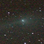
Without guiding the performance is not satisfactory. Even with a modest focal length of 380mm there are objectionable guiding errors. The frame at right shows the errors seen during a four minute exposure. Based on my first impressions I would expect to need guiding on any exposure using more than 100mm and a few minutes exposure.
Comet C/2011 L4 PanStarrs, TV-76mm and ZEQ25 mount with no guiding during a 4 minute exposureEverything connects fairly easily, a few more cables than I would like, but it is still marginally portable and not a huge chore to assemble. The challenge now is to verify the setup, configure all of the software, and to take a few photos to prove to myself that it all works properly.
A few steps here have not gone smoothly..
Configuration? There are a lot of setups to check. All of the correct software and drivers… Planetarium software, autoguiding software, camera control, ASCOM, all of the hardware drivers, etc., etc. After everything talks it is a matter of checking settings and tuning the setup with several parameters in the software and on the mount that need to be checked.
I am using PHD to do the guiding, a bit of kit I have used for a while. It works quite well with straightforward controls. It does have quite a few parameters that require checking to tune the control algorithms.
The iOptron controller has a setting for guiding speed in the menus. This is purported to be a fraction of sidereal speed by the manual, up to 100%, but the menu reads as if it is 100x on the controller. I suspect the manual is correct here, will need to test.
The first issue cropped up fairly quickly. I could get no motion from the mount while sending corrections with the STi. PHD was unable to calibrate, no motion. I attempted to use the manual controls in PHD with similar lack of motion. (See update below)
To troubleshoot I needed to make sure that the guide port on the ‘scope worked. I grabbed a Losmandy hand controller and connected it to the ZEQ25 guide port. This worked, the port was working properly and I could see what the guide speed setting on the controller really meant. It looks like 100x is 100% of siderial speed, or close enough.
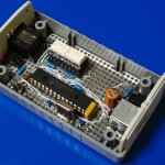
A copy of Gene Nolan’s USB to ST-4 guiding adapterI have another device I could try, a USB to ST4 adapter designed by Gene Nolan. This is also supported by PHD Guide and ASCOM driver framework is always installed on my imaging computer. After some issues with finding the correct cable setup the USB to ST4 adapter worked just fine.
Parameter
Value
RA Aggressiveness
100
RA Hysteresis
10
Max RA Duration
750ms
Search Region
15pix
Min Motion
0.1pix
Calibration Step
2000ms
Time Lapse
0ms
Dec Guide Mode
Auto
Dec Algorithm
Resist
Dec Slope Weight
5
Max Dec Duration
750ms
Star Mass Tolerance
0.5
Noise Reduction
None
PHD Guiding Paramters for STi w/100mm lens and iOptron ZEQ25
At this point I can calibrate and guide with good results. I am out of USB ports on the laptop, and had to unplug the mouse, but at least it is working.
Some tuning of the parameters in PHD has started to result in very nice guiding graphs and some excellent test images. These could probably be refined a bit more, but they are working for now. The PHD help menu has a fairly good description of each of the parameters, there is also a great guide to PHD on the Rose City Astronomers website.
Guiding Test: 240sec with a TV-76 and 60D on a ZEQ25 mountA 100% crop of an image is included at the left, nothing exciting, just a section of starfield near Vega. What is nice about the images is the perfectly round stars. The image was taken at 384mm effective focal length. Will need to do this again with the AT6RC at 1096mm for a more stringent test.
It is really necessary to set the autoguide rate to 100% when using shorter focal lengths. Otherwise the mount does not move very far during each calibration step, as a result calibrations take a very long time and will sometimes fail.
Another observation. When guiding near the pole, shooting comet PanSTARRS at near +80° declination, I encountered very regular declination errors using PHD. Every couple minutes the dec error would deviate by about a pixel, alternating in each direction. Shutting off the declination correction worked pretty well, the mount was polar aligned accurately enough that there was very little declination drift.
I still have yet to understand just why the STi will not directly interface with the ZEQ25, something in the ratings of the photo-isolators used in the STi? The manual simply states these are good to 25mA and 25V, which seems generous for the task. It may be in the voltage levels, I did discover that the iOptron uses 3.3V on the guide port. Perhaps the STi will not pull down low enough for a valid low logic level? I built the USB to ST-4 adapter with MOSFET optocouplers, these can switch harder than standard photo transistors.
UPDATE– The interface issue was just a cabling problem. The same cable I use with my Losmandy G11 does not work, it is flipped from the pinout needed for the ZEQ25. With a corrected cable I now connect the STi directly to the guide port on the ZEQ… It works.
A rigid mount to adapt the TeleVue-76 to the SBIG STi autoguider? I need such a solution, I have both of these bits of kit that need to be wed together for the minimal astrophoto setup. As I am unlikely to find such a part commercially, I would have to make it myself.
Another couple hours in the machine shop were in order, another small pile of aluminum chips. This actually went pretty quickly, these are easy cuts to make. No tapping is required, the four holes are simply drilled through. The two hours included design and cleanup for a quick project.
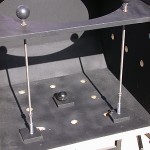
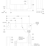
The SBIG STi to TelevVue TV-76 mountMechanical drawing for a mount to attach an SBIG STi autoguider to a TeleVue refractorI came up with the design on the fly. A piece of aluminum from the scrap bin and a couple quick measurements of the ‘scope and guider. I simply cut aluminum until it seemed about right. It was only after the fact that I produced a drawing of the finished item.
The TV-76 has a rather non-standard mounting point on top for accessories like this. A pair of #10-32 threaded holes, 0.75″ apart and located in a slot 0.625″ wide milled into the mounting ring. This seems simple enough. An adapter made for the TV-76 should work with any of the TeleVue refractors that use this mounting. Another concern is that the solution must also be very rigid, any flexure between the autoguider and the telescope will result in smeared stars.
The design assumes that you have the additional guiding kit sold by SBIG for the STi autoguider. This provides the mounting rings that clamp the camera body.
The hardware required will be two ¼-20 x 1½” socket head cap screws, and two #10-32 x 1″ socket head cap screws. A pair of plastic press on caps convert the #10 screws to knobs. All parts you can find in a neighborhood hardware store.
The mount is 1.5″ high to set the autoguider away from the main OTA, as to not encounter any vignetting. This also allows space to get fingers onto the mounting knobs. The dimensions are chosen so that standard screws protrude by just the right amount. I messed this up on the one I made, machining the center to far. As a result a few washers are needed for the screws that mate with the refractor. This is fixed in the mechanical drawing.
To co-boresight the TV-76 with the autoguider it was necessary to slip a 1/4″ washer between the mount and the rear ring as a shim. With that in place the same object is centered in both fields of view. The STi has a 2.7° x 2.2° field when used with the 100mm lens supplied in the SBIG accessory kit. With this wide field of view it also serves as a finder to locate and frame the photographic target.
It assembles nicely, a good start. The true test will be the quality of the images produced by the rig.
I had been looking to acquire another astrophoto toy. The desire is for a small, portable astrophoto setup. Yes, I am aware that the words “portable” and “astrophoto” do not really belong in the same sentence, all things are relative.
Thus I have decided on the new iOptron ZEQ25. It is a new design, with some radical differences from the more traditional German equatorial mounts.
The mount is pretty small, a mere 10 pounds of steel and aluminum. Compact enough to be packed into a suitcase for air travel. Performance sufficient to do wide field astrophotography with focal lengths up to 1000mm and a DLSR camera. Perfect for use with either my TV-76 or AT6RC. Unlike my old Losmady G-11 it features a modern GOTO system and can be run from the computer.
AT6RC atop an iOptron ZEQ25 mount, note the additional counterweight necessaryThe chatter over at Cloudy Nights was promising. A few early production mounts were in the hands of some stateside amateurs, and they have been posting their impressions and images. I was particularly impressed by the measurements of periodic error with results around two arc seconds. This was a small mount that could very easily be a good astrophoto option.
I ordered the mount from the good folks at OPT. It was not yet listed in the website catalog, but a phone call confirmed they were expecting delivery of three mounts shortly. I put down my deposit. A week later I had confirmation that the mount had been received and was ready for shipment to Hawaiʻi as promised.
The original NexStar telescopes are great instruments. Ours has seen many uses, from dark skies to not so dark skies as it has been set up in the Arizona Desert, the summit of Mauna Kea, or various school yards and resorts for public viewing. It has been used as a visual instrument, a photographic ‘scope, even done a little real work.
For the most part the scope has worked well, and has been well maintained, even updated with the latest hand pad controller. But on occasion there is a problem… connection issues would crop up. The dreaded “No Response 16” or “No Response 17” errors would appear, indicating that the motor control board is not talking. This would result in having to power cycle and realign the telescope.
Lately the errors have become more problematic. The last straw was a public event I recently used the telescope for, setting up the telescope for Halloween. Continual errors plagued the evening, a constant struggle. While the scope usually tracked, I could not use GOTO as each alignment was quickly off by just enough to be useless.
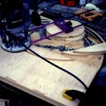
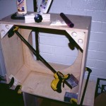
Under the hood of the NexStar showing the new cables
I have had the telescope apart too often in attempts to fix this, inspecting and re-seating the cables. This usually works, the problem will go away, for a while.
In general I like what I see inside the telescope. A well designed piece of kit with good components. Decades of taking gear apart have provided me so many examples of poor or good design. Inside the NexStar I just like what I see. The telescope is easy to get apart, just a few screws to remove each cover, exposing everything you might need to work on. The designers of this telescope obviously took pride in their work, it shows.
The exception to this is the wiring. There are a number of issues that can create trouble. Or rather there were a few issues, I just took care of that…
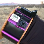
In the few days I had the camera I was determined to acquire some astrophotography test shots with the EOS-M camera. Even if it meant getting up at 3am to have some dark sky after moonset. It would have been easier a few days before, but a Pacific storm system had provided several days of overcast with occasional rain. This particular morning was just about perfect, clear skies, decent seeing and no wind to bounce the telescope around.
Astrophoto setup with AT6RC, SBIG STi autoguider and the EOS-M cameraFor testing I used the same setup I often use with my Canon 20Da or 60D. An Astro-Tech 6″ (150mm) Ritchey–Chrétien telescope riding atop a Losmandy G11 mount. A 0.8x focal reducer has T-thread at the rear allowing a Canon EOS lens adapter. To attach the EOS-M I used the Canon M Mount to EOS Mount adapter. An SBIG STi autoguider completes the setup.
The result is an f/7 optical system with 1080mm focal length. This gives a field of view of about 72×48 arc-minutes (1.2 x 0.8 degrees) on the sky when using a camera with an APS-C sensor.
Aiming a telescope at the Sun is deceptively difficult. You can not use a optical finder for risk of eye damage. Unit power finders, like a Telrad, are of little use as you can not see the projected image. Telrads can also be damaged by sunlight. In a pinch you can simply use the shadow of the telescope, positioning for a minimum shadow. This at least gets you close.
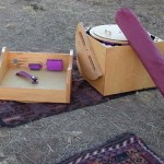
A Sun Finder mounted to a TeleVue 76mm 'scopeThe best solution is to build a finder designed just for the Sun… A Sun Finder.
There are many plans for Sun Finders posted to the web. Most use a shadow or projected point of light. The version I built is no exception, using a pinhole to project a point of light on a translucent screen. The trick is to make such a device simple and accurate.
With simple metal working capability a Sun Finder like this one can be made from sheet metal, or machined from solid aluminum. I chose the latter as I had the capability. This design uses a pinhole that projects a similarly sized dot of light at the rear of the finder. The front face or the finder, through which the pinhole is drilled, creates a shadowed area for in which the projected dot can be seen.
A Sun Finder in use with the projected dot visibleA longer distance from the pinhole to the screen will increase the sensitivity in aiming. In practice I have found that at least three inches is sufficient for most telescopes while keeping the device compact. Experimentation with the design can be entertaining and educational. No need to stick strictly with this design, just borrow the basic ideas, a lot of variations will work.
This design is based on an aluminum extrusion, a 3″ x 1.5″ channel. This save a good deal of machine work in creating the finder. As much of the machining is done along the length, a number of finders can be made at the same time. I made six finders from a seven inch scrap of extrusion out of the shop scrap pile.
Plans for the Sun FinderThe screen is made from a small piece of 1/8″ thick acrylic. Common 0.1″ thick material will work as well. One side is frosted with sandpaper to create a translucent screen. Use of a clear screen allows the solar dot to be seen from front or behind while aiming the telescope. The screen is simply secured with a glue, preferably RTV. The frosted side should be mounted towards the pinhole.
To keep the device simple there is no adjustment in aiming. If the finder is mounted reasonably well, the dot of light will be on the screen. The first time out it is necessary to first get the Sun in the field of view. You can then mark the position of the projected dot with a permanent pen (Sharpie or similar). After that aiming is simply a matter of positioning the dot on the mark. If the mark is made on the smooth side of the acrylic screen it can be easily erased and re-marked if necessary.
Done, a simple and reliable Sun Finder to work with just about any small telescope.